- Temperature parameters shall be the extreme platform envelope values for the test condition.
- Temperature Ramp Rate: LAW equip specification. If not specified, then ≤5 Deg C/min.
- Stabilization:
Non-Operational Equipment: See Part One, paragraph 5.4.2
Operational Equipment: See Part One, paragraph 5.4.1
- Altitude parameters shall be maximum platform envelope values for the test condition.
- Altitude Ramp Rate: IAW equipment specification.
- Loiter/Cruise Op Temp: Localized ambient air temp with inflight atmospheric cooling effects. IAW Platform guidance. If guidance is not provided, use the maximum operational temperature.
- Loiter/Cruise Altitude: As determined by the Program Office. This shall represent a typical long duration cruise altitude. If guidance is not provided, use the maximum operational altitude.
- Input Electrical Power:
- a. Voltage; Alternate from cycle to cycle; Nominal, High, Low, High, etc. See Tables 520.5-III, IV, V, and VI for guidance.
- b. Frequency Variation: The input electrical power frequency shall be varied from cycle to cycle. See Tables 520.5-III, V, and VI for guidance.
- Supplemental Cooling temperature and mass flow rate shall be IAW the platform/system specification. There shall be no ECS supplemental cooling for the first 2 minutes following power on.
- This shall be followed by a linear drop in the ECS supplemental cooling air temperature to the specified cooling temperature. The ECS cooling air temperature ramp rate shall be determined from the platform ECS specification. For RAM cooled compartment a thermal analysis shall be performed per the guidance in paragraph 2.2.4.1.1.a.
- It is permissible to delay the humidity ramp until the chamber temperature reaches 0 C.
- Vibration is an integral part of the flight environment. Although not shown on the above table, when added to the test the vibration levels shall be representative of the functional vibration levels for the specific phase of the mission.
MIL-STD-810H
METHOD 520.5
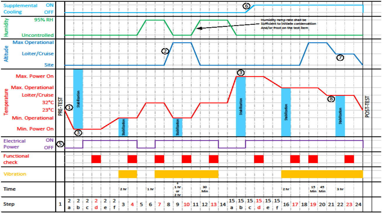
Figure description:
Comprehensive Environmental Test Profile Graph
Environmental Test Profile
Legend
- Supplemental Cooling — color: cyan; symbol: Solid line
- Humidity — color: green; symbol: Solid line
- Altitude — color: blue; symbol: Solid line
- Temperature — color: red; symbol: Solid line
- Electrical Power — color: purple; symbol: Solid line
- Functional check — color: red; symbol: Solid bar
- Vibration — color: yellow; symbol: Solid bar
- Stabilization — color: light blue; symbol: Shaded region
Annotations
- 1 (text_label - position: Start of temperature ramp profile)
- 2 (text_label - position: Altitude ramp up to Max Operational)
- 3 (shaded_area - position: Indicates stabilization periods marked with light blue shading)
- 5 (text_label - position: Electrical Power profile line)
- 6 (text_label - position: Supplemental Cooling ramp from OFF to ON)
- 7 (text_label - position: Altitude ramp down to Site level)
- 8 (text_label - position: Temperature stabilization at 23°C)
- Humidity Note (text_label - position: Humidity ramp rate shall be sufficient to initiate condensation And/or frost on the test item)
| Step | Time (Duration) | Supplemental Cooling | Humidity | Altitude | Temperature | Electrical Power | Functional check | Vibration |
|---|---|---|---|---|---|---|---|---|
| 1 | OFF | Uncontrolled | Site | ~23°C (ambient) | OFF | No | No | |
| 2a | OFF | Uncontrolled | Site | Ramp to Min. Power On | OFF | No | No | |
| 2b | OFF | Uncontrolled | Site | Min. Power On (Stabilization) | ON | No | No | |
| 2c | OFF | Uncontrolled | Site | Min. Power On | ON | No | No | |
| 2d | OFF | Uncontrolled | Site | Min. Power On | ON | Yes | No | |
| 2e | OFF | Uncontrolled | Site | Min. Power On | ON | No | No | |
| 2f | OFF | Uncontrolled | Site | Min. Power On | ON | No | No | |
| 3 | 2 hr | OFF | Uncontrolled | Site | Ramp to Min. Operational (Stabilization) | ON | No | Yes |
| 4 | OFF | Uncontrolled | Site | Min. Operational | ON | Yes | Yes | |
| 5 | OFF | Uncontrolled | Site | Ramp to 23°C | ON | No | No | |
| 6 | 1 hr | OFF | Uncontrolled | Site | 23°C | ON -> OFF | No | No |
| 7 | OFF | Ramp to 95% RH | Site | Ramp to 32°C | OFF -> ON | No | No | |
| 8 | OFF | 95% RH | Site | 32°C | ON | Yes | Yes | |
| 9 | 1 hr or 2 hr | OFF | Ramp to Uncontrolled | Ramp to Max Operational | Ramp to Min. Operational (Stabilization) | ON | No | Yes |
| 10 | OFF | Uncontrolled | Max Operational | Min. Operational | ON | Yes | Yes | |
| 11 | OFF | Ramp to 95% RH | Ramp to Site | Ramp to 32°C | ON -> OFF | No | Yes | |
| 12 | 30 Min | OFF | 95% RH | Site | 32°C | OFF -> ON | No | Yes |
| 13 | OFF | Ramp to Uncontrolled | Site | Ramp to Max Power On | ON | Yes | Yes | |
| 14 | OFF | Uncontrolled | Site | Max Power On to Max Operational | OFF | No | No | |
| 15a | OFF | Uncontrolled | Site | Max Operational | OFF | No | No | |
| 15b | Ramp to ON | Uncontrolled | Site | Max Operational (Stabilization) | ON | No | No | |
| 15c | ON | Uncontrolled | Site | Max Operational | ON | No | No | |
| 15d | ON | Uncontrolled | Site | Max Operational | ON | Yes | No | |
| 15e | ON | Uncontrolled | Site | Max Operational | ON | No | No | |
| 15f | ON | Uncontrolled | Site | Max Operational | ON | No | No | |
| 16 | 2 hr | ON | Uncontrolled | Site | Ramp to Loiter/Cruise (Stabilization) | ON | No | Yes |
| 17 | ON | Uncontrolled | Site | Loiter/Cruise | ON | Yes | Yes | |
| 18 | ON | Uncontrolled | Ramp to Max Operational | Ramp to 32°C | ON | No | Yes | |
| 19 | 15 Min | ON | Uncontrolled | Max Operational | 32°C | ON | Yes | Yes |
| 20 | 45 Min | ON | Uncontrolled | Ramp to Loiter/Cruise | Ramp to 23°C | ON | No | Yes |
| 21 | ON | Uncontrolled | Loiter/Cruise | 23°C | ON | No | Yes | |
| 22 | 3 hr | ON | Uncontrolled | Ramp to Site | 23°C (Stabilization) | ON | No | Yes |
| 23 | ON | Uncontrolled | Site | 23°C | ON | Yes | Yes | |
| 24 | ON | Uncontrolled | Site | Ramp down | ON | No | Yes |
Figure 520.5-3a. Platform Envelope Option 1 Profile Example (See notes for additional information.)
MIL-STD-810H
METHOD 520.5
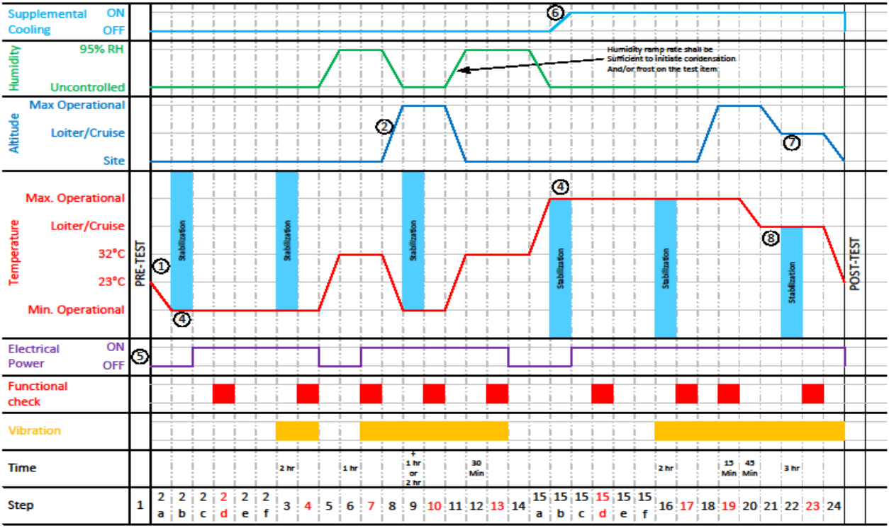
Figure description:
Environmental Test Profile Chart
Environmental Test Profile
Legend
- Supplemental Cooling — color: light blue; symbol: Solid line
- Humidity — color: green; symbol: Solid line
- Altitude — color: blue; symbol: Solid line
- Temperature — color: red; symbol: Solid line
- Electrical Power — color: purple; symbol: Solid line
- Functional check — color: red; symbol: Solid block
- Vibration — color: orange; symbol: Solid block
- Stabilization — color: cyan; symbol: Shaded vertical area
Annotations
- (1 (text_label - position: Step 2a: Temperature start of ramp down))
- (2 (text_label - position: Step 7: Altitude start of ramp up))
- (3 Humidity ramp rate shall be sufficient to initiate condensation And/or frost on the test item (text_label - position: Steps 5 and 10 humidity ramps))
- (4 Stabilization (shaded_area - position: Steps 2, 5, 9, 15, 22))
- (5 (text_label - position: Electrical Power start))
- (6 (text_label - position: Step 15: Supplemental Cooling start of ramp up))
- (7 (text_label - position: Step 20: Altitude start of ramp down))
- (8 (text_label - position: Step 20: Temperature start of ramp down))
| Step | Supplemental Cooling | Humidity | Altitude | Temperature | Electrical Power | Functional check | Vibration | Time |
|---|---|---|---|---|---|---|---|---|
| 1 | OFF | Uncontrolled | Site | 23°C | OFF | Inactive | Inactive | |
| 2a | OFF | Uncontrolled | Site | Ramp to Min. Operational | OFF | Inactive | Inactive | |
| 2b | OFF | Uncontrolled | Site | Min. Operational | ON | Inactive | Inactive | |
| 2c | OFF | Uncontrolled | Site | Min. Operational | ON | Inactive | Inactive | |
| 2d | OFF | Uncontrolled | Site | Min. Operational | ON | Active | Inactive | |
| 2e | OFF | Uncontrolled | Site | Min. Operational | ON | Inactive | Inactive | |
| 2f | OFF | Uncontrolled | Site | Min. Operational | ON | Inactive | Inactive | |
| 3 | OFF | Uncontrolled | Site | Min. Operational | ON | Inactive | Active | 2 hr |
| 4 | OFF | Uncontrolled | Site | Min. Operational | ON | Active | Active | |
| 5 | OFF | Ramp to 95% RH | Site | Ramp to 32°C | OFF | Inactive | Inactive | |
| 6 | OFF | 95% RH | Site | 32°C | OFF | Active | Inactive | 1 hr |
| 7 | OFF | 95% RH | Ramp to Max Operational | 32°C | ON | Inactive | Active | |
| 8 | OFF | Ramp to Uncontrolled | Max Operational | Ramp to Min. Operational | ON | Inactive | Active | |
| 9 | OFF | Uncontrolled | Max Operational | Min. Operational | ON | Active | Active | + 1 hr or 2 hr |
| 10 | OFF | Ramp to 95% RH | Ramp to Site | Ramp to 32°C | ON | Inactive | Active | |
| 11 | OFF | 95% RH | Site | 32°C | ON | Active | Active | 30 Min |
| 12 | OFF | Ramp to Uncontrolled | Site | 32°C | ON | Inactive | Active | |
| 13 | OFF | Uncontrolled | Site | 32°C | OFF | Active | Active | |
| 14 | OFF | Uncontrolled | Site | Ramp to Max. Operational | OFF | Inactive | Inactive | |
| 15a | Ramp to ON | Uncontrolled | Site | Max. Operational | OFF | Inactive | Inactive | |
| 15b | ON | Uncontrolled | Site | Max. Operational | ON | Inactive | Inactive | |
| 15c | ON | Uncontrolled | Site | Max. Operational | ON | Inactive | Inactive | |
| 15d | ON | Uncontrolled | Site | Max. Operational | ON | Active | Inactive | |
| 15e | ON | Uncontrolled | Site | Max. Operational | ON | Inactive | Inactive | |
| 15f | ON | Uncontrolled | Site | Max. Operational | ON | Inactive | Inactive | |
| 16 | ON | Uncontrolled | Site | Max. Operational | ON | Inactive | Active | 2 hr |
| 17 | ON | Uncontrolled | Site | Max. Operational | ON | Active | Active | |
| 18 | ON | Uncontrolled | Ramp to Max Operational | Max. Operational | ON | Inactive | Active | |
| 19 | ON | Uncontrolled | Max Operational | Max. Operational | ON | Active | Active | 15 Min |
| 20 | ON | Uncontrolled | Ramp to Loiter/Cruise | Ramp to Loiter/Cruise | ON | Inactive | Active | 45 Min |
| 21 | ON | Uncontrolled | Loiter/Cruise | Loiter/Cruise | ON | Inactive | Active | |
| 22 | ON | Uncontrolled | Loiter/Cruise | Loiter/Cruise | ON | Inactive | Active | 3 hr |
| 23 | ON | Uncontrolled | Loiter/Cruise | Loiter/Cruise | ON | Active | Active | |
| 24 | ON | Uncontrolled | Ramp to Site | Ramp to 23°C | ON | Inactive | Active | |
| POST-TEST | ON | Uncontrolled | Site | 23°C | ON | Inactive | Inactive |
Notes: The chart represents a comprehensive environmental test profile including temperature, humidity, altitude, vibration, and electrical power states across 24 defined steps plus pre- and post-test phases.
Figure 520.5-3b. Platform Envelope Option 2 Profile Example (See notes for additional information.)
Figures 520.5-3a and 520-3b. Notes:
- Temperature Ramp Rate: IAW equipment or platform(s) specification. If not specified then <5 Deg C/min.
- Altitude Ramp Rate: IAW equipment or platform(s) specification.
- Altitude Ramp Rate: HLV equipment or platform(s) specification.
- Option 1 applies materiel which, during its life cycle, is expected to be powered "ON" at temperatures either less than or greater than the normal operational temperature. This includes materiel that is powered "ON" concurrent with aircraft startup or that is powered "ON" while the aircraft is on the tarmac in a thermally ground soaked condition. Unless otherwise specified, the minimum and maximum start up temperatures will generally equate to the minimum and maximum ground soak temperatures (Figure 520.5-3a).
- Option 2 applies to materiel which is powered “ON” during flight operations after the aircraft temperature has stabilized at its normal operational temperature. (Figure 520.5-3b)
- Input Electrical Power:
a.
- Voltage: Alternate from cycle to cycle; Nominal, High, Low, High, etc. See Tables 520.5-III, IV, V, and VI for guidance.
- a. Voltage: Alternate from cycle to cycle, Nominal, High, Low, High, etc. See Tables 520.5-III, IV, V, and VI for guidance. b. Frequency Variation: The input electrical power frequency shall be varied from cycle to cycle. . See Tables 520.5-III, V, and VI for guidance.
Note: Flight critical equipment may be required to operate under abnormal and/or emergency voltage condition. See Table IV and MIL-STD-704 for the appropriate levels. See paragraph 2 2.4.4. for additional guidance.
- Supplemental Cooling temperature and mass flow rate shall be IAW the platform/system specification. There shall be no ECS supplemental cooling for the first 2 minutes following power on. This shall be followed by a linear drop in the ECS supplemental cooling air temperature to the specified cooling temperature. The ECS cooling air temperature ramp rate shall be determined from the platform ECS specification. For RAM cooled compartment a thermal analysis shall be performed per the guidance in paragraph 2.2.4.1.1.a.
- Loiter Altitude: IAW Platform guidance. If guidance is not provided, use the maximum operational altitude.
- Loiter Altitude: IAW Platform guidance. If guidance is not provided, use the maximum operational altitude.
- Loiter Temperature: IAW Platform guidance and location of equipment. If guidance is not provided, use the maximum operational temperature.
- Vibration may be performed separately with temperature. Vibration is intended to be tailored for the test items specific rotorcraft and/or fixed wing application and the levels should be in accordance with the levels expected during the specific mission segments.
- It is preferred that consecutive cycles be run continuously; however, if test chamber operations preclude continuous operation, then the transition from high altitude to site, and from loiter temperature to minimum temperature shall be completed prior to interrupting the cycles. These conditions shall be maintained until the cycle is resumed.
- Pre-Test, Post-test and Functional tests are performed to verify consistent satisfactory performance throughout the test. Pre and Post tests are generally the same. Functional tests, especially during altitude exposure, may be dependent on chamber access. These tests should be tailored per guidance in Part One.
- For External stores/munitions the solar equivalent temperature may be used to determine the high altitude temperature parameters. Referenced JOTP-012.
- Humidity: The humidity ramp rate for steps 5, 8, and 15A shall track the temperature ramp. The humidity ramp rate for step 11 shall be sufficient to initiate condensation and/or frost on the test item.