| Procedure | Test Methodology | ||||||
|---|---|---|---|---|---|---|---|
| Drop1 | Classical Pulse | SRS | TWR | ||||
| Half- Sine2 | Trapezoidal | TP Sawtooth | |||||
| I | Functional Shock | X | X | X | X | ||
| II | Transportation Shock | X | X | X | |||
| III | Fragility | X | X | ||||
| IV | Transit Drop | X | |||||
| V | Crash Hazard Shock3 | X | X | X | |||
| VI | Bench Handling | X | |||||
| VII | Pendulum Impact4 | X | |||||
| VIII | Catapult Launch/ Arrested Landing5 | X | |||||
- Note 1. The Drop test includes vertical free fall towers, impact machines, and other test methods with similar equipment.
Note 2. High Speed Craft is a special case of Functional Shock that is specified in terms of classical half-sine.
Note 3. In some cases the Crash Hazard Shock may be evaluated by a constant acceleration, see paragraph 2.2.2e.
Note 4. Pendulum Impact is a test item with horizontal motion that impacts a stationary barrier.
Note 5. A Catapult Launch/Arrested Landing test can be based on a measured waveform or a two second damped (Q=20) sine burst of required amplitude and frequency, see the test procedure.
516.8 -VI: Limited Application Requirements by Craft Size¹
| Craft Size | Location | |||
|---|---|---|---|---|
| Length (ft) | Weight (Klbs) | Longitudinal Center of Gravity (LCG) | Coxswain | Bow |
| 65-85 | 105-160 | 10 G | 15 G | 20 G |
| 40-70 | 35-70 | 10 G | 15 G | 15 G |
| 35-40 | 14-25 | 15 G | 15 G | 20 G |
Note 1. The half-sine classical pulse specified for HSC may not be substituted by an SRS equivalent complex pulse.
516.8 -VII Procedure II - Transportation shock test sequence1,2,3
| On Road (5000 km)4 Terminal Peak Sawtooth Pulse Duration: 11 ms | Off Road (1000 km)4 Terminal Peak Sawtooth Pulse Duration: 5 ms | |||
|---|---|---|---|---|
| Amplitude (G-Pk) | Number of Shocks | Amplitude (G-Pk) | Number of Shocks | |
| 5.1 | 42 | 10.2 | 42 | |
| 6.4 | 21 | 12.8 | 21 | |
| 7.6 | 3 | 15.2 | 3 | |
- Note 1: The shocks set out in Table 516.8-VII must always be carried out together with ground transportation vibration testing as specified in Method 514.8, Category 4 and/or Category 20.
- Note 2: The above tabulated values may be considered for both restrained cargo and installed materiel on wheeled and tracked vehicles. Transportation shock associated with two-wheeled trailers may exceed off-road levels as defined.
- Note 3: The shock test schedule set out in Table 516.8-VII can be undertaken using either terminal peak sawtooth pulses applied in each sense of each orthogonal axis, or a synthesis based on the corresponding SRS that encompasses both senses of each axis.
- Note 4: The above number of shocks is equivalent to the following distances: a) On-road vehicles: 5000 km; b) Off-road vehicles: 1000 km. If greater distances are required, more shocks must be applied in multiples of the figures above.
MIL-STD-810H
METHOD 516.8
516.8 -IX. Logistic Transit Drop Test¹
| Weight of Test Item & Case kg (lbs) | Largest Dimension cm (in.) | Notes | Height of Drop, h cm (in.) | Number of Drops |
|---|---|---|---|---|
| Under 45.4 (100) Man-packed or man-portable | Under 91 (36) | 122 (48) | Drop on each face, edge and corner; total of 26 drops5 | |
| 91 (36) & over | 76 (30) | |||
| 45.4–90.8 (100–200) inclusive | Under 91 | 76 (30) | Drop on each corner; total of eight drops | |
| 91 (36) & over | 61 (24) | |||
| 90.8–454 (200–1000) inclusive | Under 91 | 61 (24) | ||
| 91–152 (36–60) | 2 | 61 (24) | ||
| Over 152 (over 60) | 2 | 61 (24) | ||
| Over 454 (1000) | No limit | 3 4 | 46 (18) | Drop on each bottom edge. Drop on bottom face or skids; total of five drops |
- Note 1: Perform drops from a quick-release hook or drop tester. Orient the test item so that, upon impact, a line from the struck corner or edge to the center of gravity of the case and contents is perpendicular to the impact surface. The default drop surface is steel backed by concrete. Concrete or 5 cm (2 in) plywood backed by concrete may be selected if (a) a concrete or wood surface is representative of the most severe service conditions or (b) it can be shown that the compressive strength of the impact surface is greater than that of the test item impact point(s). Note that the shorter shock duration associated with the steel impact surface may not excite all test item resonant modes.
- Note 2: With the longest dimension parallel to the floor, support the transit, or combination case with the test item within, at the corner of one end by a block 13 cm (five inches) in height, and at the other corner or edge of the same end by a block 30 cm (12 inches) in height. Raise the opposite end of the case to the specified height at the lowest unsupported corner and allow it to fall freely.
- Note 3: While in the normal transit position, subject the case and contents to the edgewise drop test as follows (if the normal transit position is unknown, orient the case so the two longest dimensions are parallel to the floor):
Edgewise drop test: Support one edge of the base of the case on a sill 13-15 cm (five to six inches) in height. Raise the opposite edge to the specified height and allow it to fall freely. Apply the test once to each edge of the base of the case (total of four drops).
- Note 4: For shelters without shock attenuated skids, the drop height may be reduced to 15 cm (6 in) with a 10 cm (4 in) sill for edgewise drops.
- Note 5: If desired, divide the 26 drops among no more than five test items (see paragraph 4.6.5.1).
MIL-STD-810H
METHOD 516.8
516.8 -X. Tactical Transport Drop Test
| Scenario | Category | Impact Velocity (m/sec) | Drop Height1 (m) | Configuration | # Drops / Orientation 3,6 | Impact Surface | |
|---|---|---|---|---|---|---|---|
| Ship Transport | Storage and transport to theatre storage area, transport by ship | 5.4 (17.7 ft/sec) | 1.5m (5 ft) | Packaged6 | (minimum of 3) | Flat bottom and two faces.4 | Steel7,8 backed by concrete |
| Unpackaged Handling | Infantry and man- carried equipment | 5.4 (17.7 ft/sec) | 1.5m (5 ft) | Unpackaged | 5 | Steel7,8 backed by concrete | |
| Packaged Handling | Loading and offloading from side of transport vehicle - transport by truck, forklift, & helicopter | 6.4 (21 ft/sec) | 2.1m (7 ft) | Packaged6 | 5 | Flat bottom, two faces4 and two edges3 | Steel7,8 backed by concrete |
| Helicopter | Underslung load, quick release onto land or ship | 6.4 (21 ft/sec) | 2.1m (7 ft) | Packaged6 | 1 | Flat bottom | Steel7,8 backed by concrete |
| Parachute Drop2 | Low velocity drop | 8.7 (28.5 ft/sec) | 3.8m (12.6 ft) | Packaged with appropriate honeycomb or other shock absorbing system used in delivery | 1 | Flat bottom | Concrete |
| Parachute Drop | High velocity drop | 27.3 (90 ft/sec) | 38.1m (125 ft) | Concrete | |||
- Note 1: The test is not intended to encompass all credible accident conditions or severe mishandling conditions. Where the drop heights quoted are exceeded by those specified elsewhere in the table or for other phases of Service, the higher values should be substituted.
- Note 2: Drop heights are provided for simulated parachute drops. This test may not fully address certain effects that can occur during parachute drops in high wind conditions. Consider different drop height and angles of impact to address these issues. Drop from aircraft may be required for airdrop certification.
- Note 3: Sufficient assets are required to test in each of the orientations specified. Five standard drop orientations are listed in Table XII and illustrated in Figure 8. Consider other drop orientations if expected to have a greater damage potential. Expose each item to no more than 2 drops.
Note 4: For munitions, the two faces shall be the forward and aft ends of the munition.
Note 5: For munitions, the two edges shall be at 45 degrees on the forward and aft ends.
Note 6: Unpackaged if required by LCEP or Test Plan.
- Note 7: The default drop surface is steel backed by concrete. Concrete or 5 cm (2 in) plywood backed by concrete may be selected if (a) a concrete or wood surface is representative of the most severe service conditions or (b) it can be shown that the compressive strength of the impact surface is greater than that of the test item impact point(s). Note that the shorter shock duration associated with the steel impact surface may not excite all test item resonant modes.
- Note 8: A steel impact surface shall have a Brinell hardness of at least 200. For test items less than 454 kg (1000 lbs) the steel plate shall be at least 2.5 cm (1 in) thick, otherwise it shall be at least 7.6 cm (3 in) thick.
| Scenario | Category | Impact Velocity (m/sec) | Drop Height (m) | Configuration | # Drops / Orientation4,5 | |
|---|---|---|---|---|---|---|
| Helicopter | External Carriage on Helicopter | 6.4 (21 ft/sec) | 2.1m (7 ft) | Unpackaged | Flat Bottom, two faces² and two edges³ | |
| Military Land Vehicles | Includes weapons loading and off loading | 7.7 (25.3 ft/sec) | 3.05m (10 ft) | Unpackaged | 5 | |
| Aircraft | External Carriage on Fixed Wing Aircraft | 7.7 (25.3 ft/sec) | 3.05m (10 ft) | Unpackaged | ||
| Crane | Accidental Crane Drop | 15.5 (50.9 ft/sec) | 12.2m (40 ft) | Packaged¹ | ||
| Ship Transport | Shipboard Loading | 15.5 (50.9 ft/sec) | 12.2m (40 ft) | Packaged¹ | (minimum of 3) | Flat Bottom and two faces.² |
| Ship Aircraft Carrier | Shipboard Loading and Handling | 22.1 (72.5 ft/sec) | 25m (82 ft) | Packaged¹ | 5 | Flat Bottom, two faces² and two edges³ |
- Note 1: Unpackaged if required by LCEP or Test Plan.
- Note 2: For munitions, the two faces shall be the forward and aft ends of the munition.
- Note 3: For munitions, the two edges shall be at 45 degrees on the forward and aft ends.
- Note 4: Sufficient assets are required to test in each of the orientations specified. Five standard drop orientations are shown listed in Table 10 and illustrated in Figure 8. Other drop orientations should be considered if expected to have a greater damage potential. Each item should be exposed to no more than 2 drops.
Note 5: The default drop surface is steel backed by concrete. Concrete or 5 cm (2 in) plywood backed by concrete may be selected if (a) a concrete or wood surface is representative of the most severe service conditions or (b) it can be shown that the compressive strength of the impact surface is greater than that of the test item impact point(s). Note that the shorter shock duration associated with the steel impact surface may not excite all test item resonant modes.
| Drop | Rectangular Packages | Cylindrical Packages |
|---|---|---|
| 1 | Flat Bottom | Horizontal (Side 1) |
| 2 | Face 1: (Left End) | Face 1: (Fwd End/Top) |
| 3 | Face 2: (Right End) | Face 2: (Aft End/Bottom) |
| 4 | Edge 1: (Bottom Right End Edge) | Edge 1: (Aft End Bottom Edge (45 Deg)) |
| 5 | Edge 2: (Top Left Edge) | Edge 2: Fwd End Top Edge (45 Deg)) |
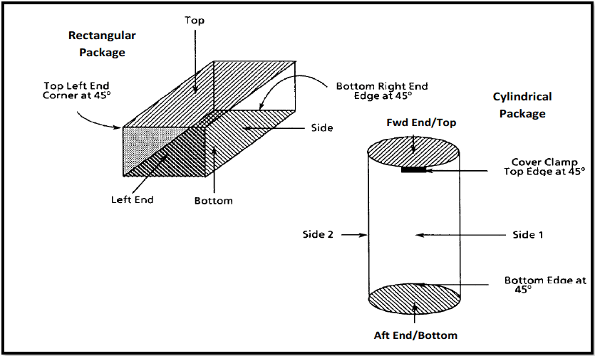
Figure description:
Figure 516.8-8: Standard drop orientations for rectangular and cylindrical packages.
Rectangular Package Orientations:
- Faces: Top, Bottom, Side, Left End
- Edges/Corners:
- Top Left End Corner at 45°
- Bottom Right End Edge at 45°
Cylindrical Package Orientations:
- Ends: Fwd End/Top, Aft End/Bottom
- Sides: Side 1, Side 2
- Edges:
- Cover Clamp Top Edge at 45°
- Bottom Edge at 45°
Figure 516.8-8. Standard drop orientations for rectangular and cylindrical packages.
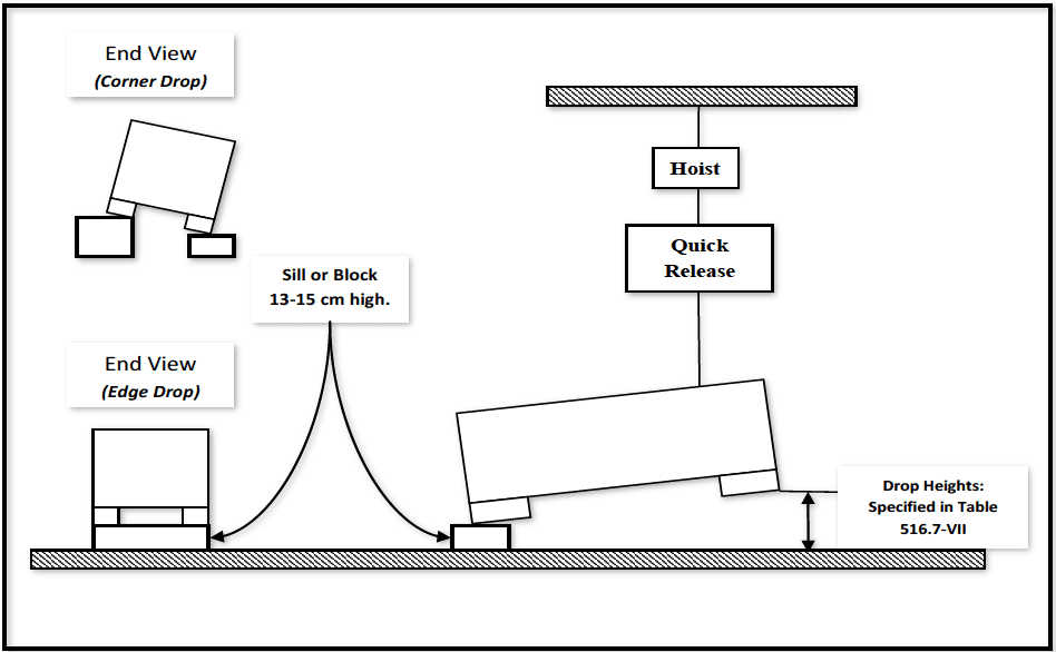
Figure description:
Figure 516.8-9: Illustration of edge drop configuration
- Test Components:
- Hoist and Quick Release: Mechanism used to lift and release the test article.
- Sill or Block: Support used for one side of the article, measuring 13-15 cm high.
- Test Article: Shown in tilted positions for drop testing.
- Configurations Illustrated:
- Edge Drop: Main side view and end view showing the article resting on a block on one side.
- Corner Drop: End view showing the article tilted and supported at a corner.
- Key Parameters:
- Sill/Block Height: 13-15 cm.
- Drop Heights: Defined by Table 516.7-VII.
Figure 516.8-9. Illustration of edge drop configuration (corner drop end view is also illustrated).
516.8 -XIII. Terminal peak sawtooth default test parameters for
Procedure V – Crash Hazard (refer to Figure 516.8-3).
Test: Minimum Peak Value and Pulse Duration: Am (G-Pk) & TD(ms): Flight Vehicle Materiel1: Ground Materiel1:
Procedure V -Crash Hazard: Flight Vehicle Materiel1: 40 G Flight Vehicle Materiel1: 11 ms Ground Materiel1: 75 G Ground Materiel1: 6 ms
Note 1. For materiel that is shock-mounted or weighing more than 136 kg (300 lbs), an 11 ms half-sine pulse of such amplitude that yields an equivalent velocity to the default terminal peak sawtooth may be employed.