The following information is necessary to properly conduct the acoustic test.
MIL-STD-810H METHOD 515.8
515.8-3 EXTERNAL STORES TESTING
515.8-3 ACOUSTIC NOISE CHARACTERISTICS
Radiated high intensity noise is subjected to distortion due to adiabatic heating. Thus, due to heating of the high pressure peaks and cooling of the rarefaction troughs, the local speed of propagation of these pressures is modified. This causes the peaks to travel faster and the troughs to travel slower than the local speed of propagation such that, at a distance from the source, a sinusoidal wave becomes triangular with a leading shock front. This waveform is rich in harmonics and therefore the energy content is extended into a higher frequency range. It can be seen from this that it is not possible to produce a pure sinusoidal tone at high noise intensities. The same effect takes place with high intensity random noise that is commonly produced by modulating an airflow with a valve driven by a dynamic actuator. Due to velocity and/or acceleration restraints on the actuator, it is not possible to modulate the airflow at frequencies greater than about 1 kHz. Acoustic energy above this frequency, extending to 20 kHz or more, therefore results from a combination of cold air jet noise and harmonic distortion from this lower frequency modulation.
3.1 Pretest
- a. General. See the information listed in Part One, paragraphs 5.7, 5.8, 5.9, 5.11 and 5.12; and Part One, Annex A, Task 405 of this Standard.
- b. Specific to this Method.
- (1) Establish test levels and durations using projected Life Cycle Environmental Profiles, available data or data acquired directly from an environmental data-gathering program. When these data are not available, use the guidance on developing initial test severities in Annex A. Consider these overall sound pressure levels (OASPL) (Annex A, Table 515.8A-I) as initial values until measured data are obtained. The test selected may not necessarily be an adequate simulation of the complete environment and consequently a supporting assessment may be necessary to complement the test results.
- (2) If the test item is required to operate during the test; the operating checks required are pretest, during the test, and post test. For the pre- and post test checks, specify whether they are performed with the test item installed in the test facility. Define the details required to perform the test, including the method of attachment or suspension of the test item, the surfaces to be exposed, effect of gravity and any consequent precautions. Identify the control and monitor points, or a procedure to select these points. Define test interruption, test completion and failure criteria.
- c. Tailoring. Necessary variations in the basic test procedures to accommodate LCEP requirements and/or facility limitations.
515.8-3.1 Test Spectrum
A typical store profile is shown on Figure 515.8A-2. The applied test spectrum is shown on Figure 515.8A-3.
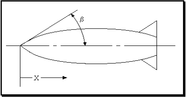
Figure description:
- Entity: Typical store profile (missile/bomb shape.
- Dimension X: Distance from the nose tip along the longitudinal axis.
- Angle β: Angle between the longitudinal axis and a tangent to the nose curve.
- Features: Curved aerodynamic body with rear stabilizing fins.
Figure 515.8A-2. Typical store profile.
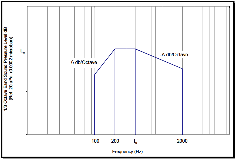
Figure description:
1/3 Octave Band Sound Pressure Level vs Frequency Ref. 20 μPa (0.0002 microbar
1/3 Octave Band Sound Pressure Level (dB
Annotations
- 6 db/Octave (text_label - position: Slope between 100 Hz and 200 Hz)
- -A db/Octave (text_label - position: Slope between Hz and 2000 Hz)
- (text_label - position: y-axis level of the plateau)
- (text_label - position: x-axis corner frequency)
- 100 (text_label - position: x = 100)
- 200 (text_label - position: x = 200)
- 2000 (text_label - position: x = 2000)
| Frequency (Hz) | 1/3 Octave Band Sound Pressure Level (dB) |
|---|---|
| 100 | 0 |
| 100 | |
| 200 | |
| 2000 | ) |
| 2000 | 0 |
Notes: The chart shows a standard noise or vibration profile defined on a logarithmic frequency scale. The profile consists of a linear increase (6 dB/octave from 100 Hz to 200 Hz, a constant level plateau () from 200 Hz to Hz, and a linear decrease (-A dB/octave from to 2000 Hz. The x-axis is Frequency in Hz and the y-axis is 1/3 Octave Band Sound Pressure Level in dB relative to 20 μPa.))
Figure 515.8A-3. One-third octave band spectrum for assembled externally carried aircraft stores.
MIL-STD-810H METHOD
3.2 During Test
- a. General. See the information listed in Part One, paragraph 5.10, and in Part One, Annex A, Tasks 405 and 406.
- b. Specific to this Method.
- (1) Collect outputs of microphones, test control averages, test item operating parameters and any other relevant transducers at appropriate test times.
- (2) Collect log/records of materiel operating parameters.
- (3) Give particular attention to interactions of the input excitation (diffuse, directional or tonal).
- (4) Record transient behavior in the input representing a test anomaly.
515.8-3.2 Test Parameters
For acoustic testing of external stores, the associated levels and definitions are shown in Table 515.8A-IV.
| A = 6 dB/Octave when f0 > 400 Hz | ||
| A = 2 dB/Octave when f0 ≤ 400 Hz | ||
| Functional Test | ||
| L0 = 20 log (q1) + 11 log (X) + 7 log (1-cos β) + G + H | (dB) | (see Notes 1, 5, 6, 7.) |
| f0 = 600 log (X/R) + C | (see Notes 2, 3.) | |
| Endurance Test | ||
| L0 = 20 log (q2/q1) + 2.5 log (N/3T) + functional level | (dB) | (see Notes 1, 5, 6, 7.) |
| f0 = 600 log (X/R) + C | (see Notes 2, 3.) | |
| Definitions | ||
| q1 = captive flight dynamic pressure (lbs/ft²) < 1800 | ||
| q2 = 1200 psf or maximum captive flight dynamic pressure (whichever is lower) (lbs/ft²) | ||
| N = maximum number of anticipated service missions (minimum N = 3) | ||
| R = local radius of store in inches | (see Note 4.) | |
| X = distance from nose of store along axis of store in inches | ||
| T = test time in hours (minimum T=1 hour unless otherwise specified) | ||
| C = -200 for locations (1) within one (D) of the aft end of the store, or (2) aft of a flow reentry point. (See Note 8); = 400 for all other locations | ||
| D = maximum store diameter in inches | (see Note 4.) | |
| β = local nose cone angle at X equals 1/tanβ = (R/X) | (see figure 515.5A-2) | |
| G = 72 unless measured data shows otherwise | ||
| E = 96 unless measured data shows otherwise | ||
| F = 84 unless measured data shows otherwise | ||
| H = 0 for 0.85 < M < 0.95; | ||
| =-3 dB for all other values of M | ||
| M = Mach number | ||
MIL-STD-810H
METHOD 515.8 ANNEX A Table 515.8A-IV. Continued.
Representative parametric values to be used for captive flight when specific parameters are not available:
| Store Type | N Endurance | Local Nose Cone Angle Degrees | q max | f₀ Nose Section | f₀ Middle Section | f₀ Aft Section |
|---|---|---|---|---|---|---|
| Air-to-Air Missile | 100 | 69 | 1600 | 500 | 1000 | 500 |
| Air-to-Ground Missile | 3 | 12 | 1600 | 800 | 630 | 630 |
| Instrument Pod | 500 | 69 | 1800 | 500 | 1000 | 500 |
| Reusable Dispenser | 50 | 11 | 1200 | 630 | 1000 | 400 |
| Demolition Bomb | 3 | 24 | 1200 | 500 | 1000 | 630 |
| Flat Nose Store | 3 | 90 | 1200 | 400 | 630 | 315 |
Notes
- Raise computed Lo level by 3 dB for a store carried in a TER cluster rack; by 5 dB for an MER cluster rack.
- If calculated fo is above 2000 Hz, use upper frequency limit of 2000 Hz. If calculated fo is below 200 Hz, use 200 Hz.
- Round off fo upward to a one-third octave center band frequency.
- For stores that do not have circular cross-sections, use the radius in the formulas that is the radius of the circle that circumscribes the cross-section of the store.
- For locations on flat nose stores (80° ≤ẞ≤90°) where X < 100:
Functional test: Lo=20 log (q1) - 6 log (X) +E+H
Endurance test: Lo = 20 log (q2) - 6 log (X) + E + 2.5 log (N/3T) + H
- For long cylindrical section, > 2D, use for locations more than one D aftward into the cylindrical section:
Functional test: Lo = 20 log (q1) + F + H
Endurance test: Lo = 20 log (q2) + F +2.5 log (N/3T) + H
- For changing radius section either aft of a long cylindrical section or when X > 100 on a flat nose store, redefine X so that X = 1 at the beginning of this section.
Functional test:
Endurance test: L₀ = 20 log (q₂) + 11 log (X) + F + 2.5 log (N/3T) + H
- A flow reentry point is the furthest upstream (forward) point of a store cross section change which results in a flow component toward the store centerline as opposed to flow away from or parallel to the store centerline.
MIL-STD-810H METHOD
3.3 Post-Test
The following post test data shall be included in the test report.
- a. General. See the information listed in Part One, paragraph. 5.13; and in Part One, Annex A, Task 406 of this Standard.
- b. Specific to this Method.
- (1) Identify any indication of failure under specified failure criteria. Account for tolerance excesses when testing large materiel, the number of simultaneous test items in Procedure I, and any other environmental conditions at which testing was carried out, if other than standard laboratory conditions.
- (2) Ensure detailed data analysis for verification of the input to the test item, i.e., the acoustic field and the response monitoring of the test item, are in accordance with the test plan.
- (3) Any deviations from the test plan.