| Vehicle Category 1/ | Forward Acceleration A (g's) 2/ | Test Level | ||||||
|---|---|---|---|---|---|---|---|---|
| Direction of Vehicle Acceleration (See Figure 513.8-2) | ||||||||
| Fore | Aft | Up | Down | Lateral | ||||
| Left | Right | |||||||
| Aircraft 3/, 4/ | 2.0 | 1.5A | 4.5A | 6.75A | 2.25A | 3.0A | 3.0A | |
| Helicopters | 5/ | 4.0 | 4.0 | 10.5 | 4.5 | 6.0 | 6.0 | |
| Manned Aerospace Vehicles 6/ | 6.0 to 12.0 7/ | 1.5A | 0.5A | 2.25A | 0.75A | 1.0A | 1.0A | |
| Aircraft Stores Carried on: | Wing/ Sponson | 2.0 | 7.5A | 7.5A | 9.0A | 4.9A | 5.6A | 5.6A |
| Wing Tip | 2.0 | 7.5A | 7.5A | 11.6A | 6.75A | 6.75A | 6.75A | |
| Fuselage | 2.0 | 5.25A | 6.0A | 6.75A | 4.1A | 2.25A | 2.25A | |
| Ground-Launched Missiles | 8/, 9/ | 1.2A | 0.5A | 1.2A' 10/ | 1.2A' 10/ | 1.2A' 10/ | 1.2A' 10/ | |
1/ Use levels specified for individual platforms and locations on/in the platforms. Use the values of this table only if platform criteria are unavailable.
2 Use levels in this column when forward acceleration is unknown. When the forward acceleration of the vehicle is known, use that value for A.
³ For carrier-based aircraft, use 4 as a minimum value for A, representing a basic condition associated with catapult launches.
4/ For attack and fighter aircraft, add pitch, yaw and roll accelerations as applicable (see paragraph 2.3.3).
For helicopters, forward acceleration is unrelated to acceleration in other directions. Test levels are based on current and near future helicopter design requirements.
6/ Manned vehicles capable of flight in the Earth's atmosphere and surrounding space environment.
When forward acceleration is not known, use the high value of the acceleration range.
8/ A is derived from the propulsion thrust curve data for maximum firing temperature.
2/ In some cases, the maximum maneuver acceleration and the maximum longitudinal acceleration will occur at the same time. When this occurs, test the materiel with the appropriate factors using the orientation and levels for the maximum (vertical) acceleration.
Where is the maximum maneuver acceleration.
MIL-STD-810H
METHOD 513.8
513.8 -II. Suggested g levels for Procedure II - Operational Test
| Vehicle Category 1/ | Forward Acceleration A (g's) 2/ | Test Level | ||||||
|---|---|---|---|---|---|---|---|---|
| Direction of Vehicle Acceleration (See Figure 513.8-2) | ||||||||
| Fore | Aft | Up | Down | Lateral | ||||
| Left | Right | |||||||
| Aircraft 3/,4/ | 2.0 | 1.0A | 3.0A | 4.5A | 1.5A | 2.0A | 2.0A | |
| Helicopters | 5/ 2.0 | 2.0 | 2.0 | 7.0 | 3.0 | 4.0 | 4.0 | |
| Manned Aerospace Vehicles 6/ | 6.0 to 12.0 7/ | 1.0A | 0.33A | 1.5A | 0.5A | 0.66A | 0.66A | |
| Aircraft Stores Carried on: | Wing/ Sponson | 2.0 | 5.0A | 5.0A | 6.0A | 3.25A | 3.75A | 3.75A |
| Wing Tip | 2.0 | 5.0A | 5.0A | 7.75A | 4.5A | 4.5A | 4.5A | |
| Fuselage | 2.0 | 3.5A | 4.0A | 4.5A | 2.7A | 1.5A | 1.5A | |
| Ground-Launched Missiles | 8/,9/ | 1.1A | 0.33A | 1.1A' 10/ | 1.1A' 10/ | 1.1A' 10/ | 1.1A' 10/ | |
1/ Use levels specified for individual platforms and locations on/in the platforms. Use the values of this table only if platform criteria are unavailable.
2 Use levels in this column when forward acceleration is unknown. When the forward acceleration of the vehicle is known, use that value for A.
³ For carrier-based aircraft, use 4 as a minimum value for A, representing a basic condition associated with catapult launches.
4/ For attack and fighter aircraft, add pitch, yaw and roll accelerations as applicable (see paragraph 2.3.3).
For helicopters, forward acceleration is unrelated to acceleration in other directions. Test levels are based on current and near future helicopter design requirements.
6 Manned vehicles capable of flight in the Earth's atmosphere and surrounding space environment.
7/ When forward acceleration is not known, use the high value of the acceleration range.
8/ A is derived from the propulsion thrust curve data for maximum firing temperature.
2' In some cases, the maximum maneuver acceleration and the maximum longitudinal acceleration will occur at the same time. When this occurs, test the materiel with the appropriate factors using the orientation and levels for the maximum (vertical) acceleration.
10/ Where A' is the maximum maneuver acceleration.
513.8 -III. Suggested g levels for Procedure III - Crash Hazard Acceleration Test.
| Vehicle/Category | Test Level (g's) ¹ | |||||
|---|---|---|---|---|---|---|
| Direction of Vehicle Acceleration (See Figure 513.8-2) | ||||||
| Fore | Aft | Up | Down | Left | Right | |
| All manned air vehicles except cargo/transport | ||||||
| Personnel capsule | 40 | 12 | 10 | 25 | 14 | 14 |
| Ejection seat | 40 | 7 | 10 | 25 | 14 | 14 |
| All other items 2/ | 40 | 20 | 10 | 20 | 14 | 14 |
| Helicopters 4/ | 20 | 20 | 10 | 20 | 18 | 18 |
| Cargo/transport | ||||||
| Pilot and aircrew seats | 16 | 6 | 7.5 | 16 | 5.5 | 5.5 |
| Passenger seats | 16 | 3 | 4 | 16 | 5.5 | 5.5 |
| Side facing troop seats | 3 | 3 | 5 | 16 | 3 | 3 |
| Personnel restraint | 10 | 5 | 5 | 10 | 3 | 3 |
| Stowable troop seats | 10 | 5 | 5 | 10 | 10 | 10 |
| All other items 2/ | 20 | 10 | 10 | 20 | 10 | 10 |
| Helicopters 4/ | 20 | 20 | 10 | 20 | 18 | 18 |
1/ Use levels specified for individual platforms and locations on/in the platforms. Use the values of this table only if platform criteria are unavailable.
2 The intent of this test is to disclose structural failures of materiel that may present a hazard to personnel during or after a crash. This test is intended to verify that materiel mounting and/or restraining devices will not fail and that sub-elements are not ejected during a crash. Use for materiel mounted in flight occupied areas and/or that could block aircrew/passenger egress or rescue personnel ingress after a crash.
- Test item function is not required following this test. Thus test items that are not suitable for other tests or field use may be used for this test. Ensure test items are structurally representative (strength, stiffness, mass, and inertia) of the production design, but need not be functional. All contents (including fluids) designed to be carried in/on the materiel should be included. Tactical restraint systems should be loaded with the maximum expected weight.
See paragraph 6.1, reference a. Some system specific crash hazard acceleration levels are provided in Table 513.8-IV.
MIL-STD-810H
METHOD 513.8
513.8 -IV. System specific g levels for Procedure III - Crash Hazard Acceleration Test
| AH-64 A & D Aircraft Crash Test Levels (g's) 1 | |||||
|---|---|---|---|---|---|
| Direction of Vehicle Acceleration | Applied Separately | Applied Simultaneously6 | Transport Acceleration Applied Separately (items not able to reach cockpit) | ||
| Up | 20 | 10 | 20 | 10 | 4.5 |
| Down | 10 | 5 | 10 | 5 | 2 |
| Lateral | ±20 | ±10 | ±10 | ±20 | 1.5 |
| Forward | 20 | 20 | 10 | 10 | 1.5 |
| Aft | 20 | 20 | 10 | 10 | 3 |
OH-58D Kiowa Warrior Aircraft Crash Test Levels (g's) (Applied Separately) ²/
| Direction of Vehicle Acceleration | Seat (200 lb per) | Cargo Equipment (items that can get into cockpit)6/ | Equipment Mounted in Aft Equipment Compartment | |
|---|---|---|---|---|
| Up | 20 | 16 | 8 | |
| Down | 10 | 8 | 4 | |
| Lateral | 20 | 16 | 8 | |
| Forward | 10 | 8 | 4 | |
| Aft | 10 | 16 | 8 | |
CH-47D/F Aircraft Crash Test Levels (g's)
| Direction of Vehicle Acceleration | Applied Separately | (g) | ||
|---|---|---|---|---|
| Up | - | |||
| Down | 8 | |||
| Lateral | 8 | |||
| Forward | 8 | |||
| Aft | - |
UH-1H Aircraft Crash Test Levels (g's)
| Direction of Vehicle Acceleration | Applied Separately | |||
|---|---|---|---|---|
| Up | 8 | |||
| Down | 4 | |||
| Lateral | ±8 | |||
| Forward | 8 | |||
| Aft | - |
UH/HH/MH-60A/L/M Aircraft Crash Test Levels (g's)
| Direction of Vehicle Acceleration | Applied Separately | Applied Simultaneously 6/ | External 6/ (in any combination) | ||
|---|---|---|---|---|---|
| Up | 20 | 10 | 20 | 10 | 6 |
| Down | 10 | 5 | 10 | 5 | 3 |
| Lateral | ±18 | ±9 | ±9 | ±18 | 3 (in) / 6 (out) |
| Forward | 20 | 20 | 10 | 10 | 6 |
| Aft | 20 | 20 | 10 | 10 | - |
| 1/ See Design Criteria Report, Report No. 77-Y-8001-3 paragraph 6.1, reference b. |
| 2/ See System Specification, Specification No. 406-947-500B paragraph 6.1, reference c. |
| 3/ See reference Structural Design Criteria, Document No. 145-SS-603 paragraph 6.1, reference d. |
| 4/ See reference System Specification, Contract DAAJ01-74-C-0175 paragraph 6.1, reference e. |
| 5/ See reference Aircraft Specification, Document No. SES-700700 paragraph 6.1, reference f. |
| 6/ Apply the worst case combination of test levels simultaneously. The requirement to test in different directions simultaneously can be accomplished through angled fixtures. |
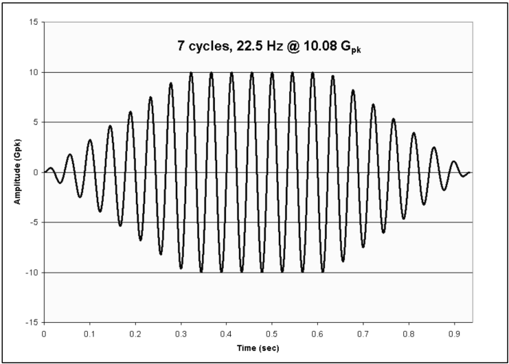
Figure description:
7 cycles, 22.5 Hz @ 10.08 Gpk
7 cycles, 22.5 Hz @ 10.08 Gpk
| Time (sec) | Amplitude (Gpk) |
|---|---|
| 0.000 | 0.0 |
| 0.011 | 0.5 |
| 0.022 | 0.0 |
| 0.033 | -1.1 |
| 0.044 | 0.0 |
| 0.056 | 1.8 |
| 0.067 | 0.0 |
| 0.078 | -2.5 |
| 0.089 | 0.0 |
| 0.100 | 3.3 |
| 0.111 | 0.0 |
| 0.122 | -4.0 |
| 0.133 | 0.0 |
| 0.144 | 4.6 |
| 0.156 | 0.0 |
| 0.167 | -5.4 |
| 0.178 | 0.0 |
| 0.189 | 6.1 |
| 0.200 | 0.0 |
| 0.211 | -6.9 |
| 0.222 | 0.0 |
| 0.233 | 7.8 |
| 0.244 | 0.0 |
| 0.256 | -8.4 |
| 0.267 | 0.0 |
| 0.278 | 8.9 |
| 0.289 | 0.0 |
| 0.300 | -9.6 |
| 0.311 | 0.0 |
| 0.322 | 10.0 |
| 0.333 | 0.0 |
| 0.344 | -10.0 |
| 0.356 | 0.0 |
| 0.367 | 10.0 |
| 0.378 | 0.0 |
| 0.389 | -10.0 |
| 0.400 | 0.0 |
| 0.411 | 10.0 |
| 0.422 | 0.0 |
| 0.433 | -10.0 |
| 0.444 | 0.0 |
| 0.456 | 10.0 |
| 0.467 | 0.0 |
| 0.478 | -10.0 |
| 0.489 | 0.0 |
| 0.500 | 10.0 |
| 0.511 | 0.0 |
| 0.522 | -10.0 |
| 0.533 | 0.0 |
| 0.544 | 10.0 |
| 0.556 | 0.0 |
| 0.567 | -10.0 |
| 0.578 | 0.0 |
| 0.589 | 10.0 |
| 0.600 | 0.0 |
| 0.611 | -10.0 |
| 0.622 | 0.0 |
| 0.633 | 9.8 |
| 0.644 | 0.0 |
| 0.656 | -9.1 |
| 0.667 | 0.0 |
| 0.678 | 8.4 |
| 0.689 | 0.0 |
| 0.700 | -7.6 |
| 0.711 | 0.0 |
| 0.722 | 6.8 |
| 0.733 | 0.0 |
| 0.744 | -6.1 |
| 0.756 | 0.0 |
| 0.767 | 5.4 |
| 0.778 | 0.0 |
| 0.789 | -4.6 |
| 0.800 | 0.0 |
| 0.811 | 3.8 |
| 0.822 | 0.0 |
| 0.833 | -3.0 |
| 0.844 | 0.0 |
| 0.856 | 2.2 |
| 0.867 | 0.0 |
| 0.878 | -1.5 |
| 0.889 | 0.0 |
| 0.900 | 0.8 |
| 0.911 | 0.0 |
| 0.922 | -0.4 |
| 0.933 | 0.0 |
Notes: The chart shows an amplitude-modulated sine wave with a 22.5 Hz frequency, featuring 7 full-amplitude cycles at approximately 10.08 Gpk. The signal ramps up from 0 to 0.32 seconds and ramps down from 0.63 to 0.94 seconds.
Figure 513.8-1. Example sine burst test specification for strength testing (from NASA-HDBK-7008).
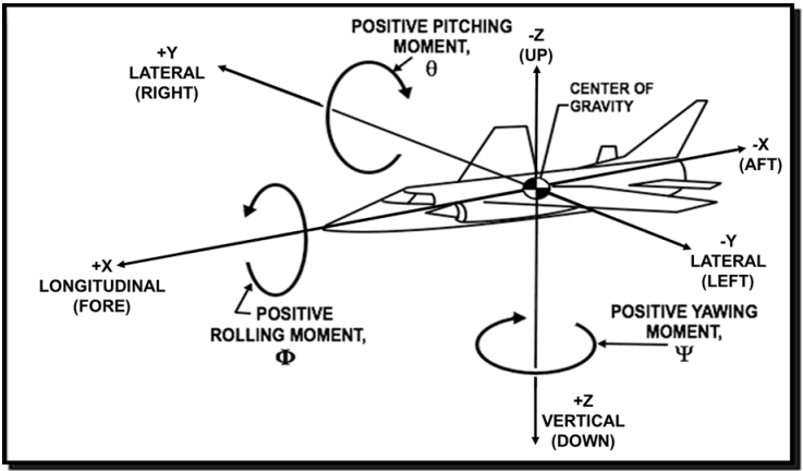
Figure description:
The image illustrates the standard coordinate system and rotational moments for an aircraft, centered on its Center of Gravity.
Linear Axes:
- X-Axis (Longitudinal: +X is Fore, -X is Aft.
- Y-Axis (Lateral: +Y is Right, -Y is Left.
- Z-Axis (Vertical: +Z is Down, -Z is Up.
Rotational Moments:
- Rolling Moment (Φ: Rotation around the X-axis.
- Pitching Moment (θ: Rotation around the Y-axis.
- Yawing Moment (Ψ: Rotation around the Z-axis.
Figure 513.8-2. Typical directions of vehicle acceleration (right hand rule).