4.3.1 Roles of Design Engineers
Design engineers conduct engineering analyses that predict responses of materiel to the stresses of the environmental life cycle. These analyses are used to prepare materiel designs that incorporate necessary resistances to environmental stresses, to modify test criteria to account for factors that cannot be fully accounted for in laboratory testing, and to interpret test results during failure analyses and redesign.
4.3.2 Roles of Test Engineers/Facility Operators
Test engineers develop test implementation plans/instructions that are carried out by other engineers or facility operators. Facility operators conduct tests according to direction established in system test planning and assessment documents and specific instructions prepared by test engineers/scientists who base their procedures on the environmental tailoring process. As a result of the tailoring process, laboratory testers will conduct only those tests that are appropriate, using exposure levels that will be neither too high nor too low because they will have been established according to the environments and levels that the materiel would be expected to see throughout its service life. In the same manner, field/fleet testers will conduct tests in those natural environments in which the materiel is expected to operate.
4.3.3 Guidance for Design and Test Engineers and Test Facility Operators
4.3.3.1 Natural environment (field/fleet) testing
4.3.3.1 Natural environment (field/fleet) testing. Plan for and conduct natural environmental field/fleet tests, and incorporating the principles of environmental tailoring information into established field/fleet procedures and facilities.
4.3.3.2 Laboratory Testing
7.1.3.2 Laboratory Testing. Plan for and conduct laboratory tests according to the tailoring information above and specific guidelines below in Part One, plus specific guidelines in each Method of Part Two of this standard.
Shipping/Transportation
Shirley F
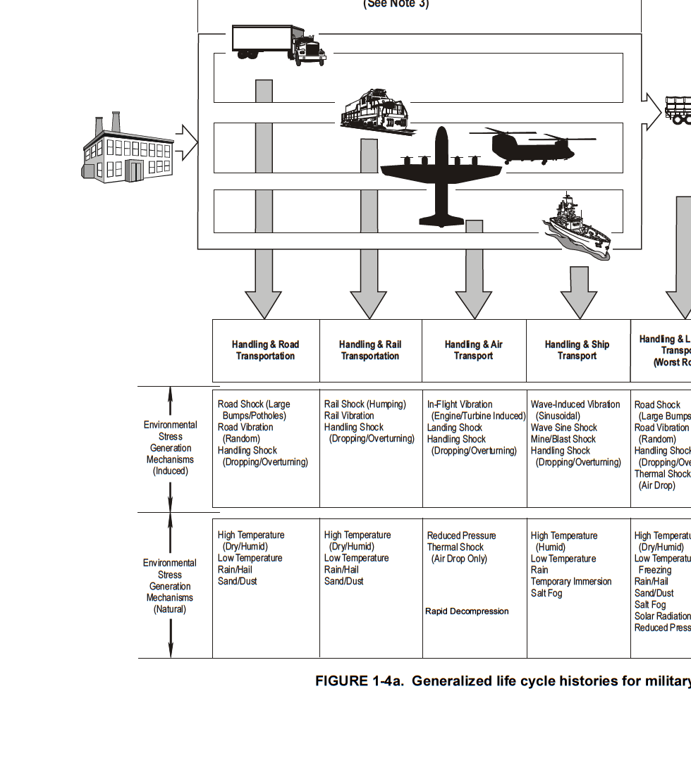
Figure description:
Generalized life cycle histories for military Environmental Stress Generation Mechanisms (Induced vs Natural
FIGURE 1-4a. Generalized life cycle histories for military...
Annotations
- (See Note 3 (text_label - position: Top center, above transportation mode icons))
| Stress Category | Handling & Road Transportation | Handling & Rail Transportation | Handling & Air Transport | Handling & Ship Transport | Handling & L... Transport (Worst R...) |
|---|---|---|---|---|---|
| Environmental Stress Generation Mechanisms (Induced) | Road Shock (Large Bumps/Potholes Road Vibration (Random Handling Shock (Dropping/Overturning))) | Rail Shock (Humping Rail Vibration Handling Shock (Dropping/Overturning)) | In-Flight Vibration (Engine/Turbine Induced Landing Shock Handling Shock (Dropping/Overturning)) | Wave-Induced Vibration (Sinusoidal Wave Sine Shock Mine/Blast Shock Handling Shock (Dropping/Overturning)) | Road Shock (Large Bumps/Potholes Road Vibration (Random Handling Shock (Dropping/Overturning Thermal Shock (Air Drop)))) |
| Environmental Stress Generation Mechanisms (Natural) | High Temperature (Dry/Humid Low Temperature Rain/Hail Sand/Dust) | High Temperature (Dry/Humid Low Temperature Rain/Hail Sand/Dust) | Reduced Pressure Thermal Shock (Air Drop Only Rapid Decompression) | High Temperature (Humid Low Temperature Rain Temporary Immersion Salt Fog) | High Temperature (Dry/Humid Low Temperature Freezing Rain/Hail Sand/Dust Salt Fog Solar Radiation Reduced Pressure) |
Notes: The figure illustrates various transportation modes (truck, rail, air, ship and the corresponding induced and natural environmental stressors. The fifth column header and main title are partially cut off.)
Shipping/Trailer
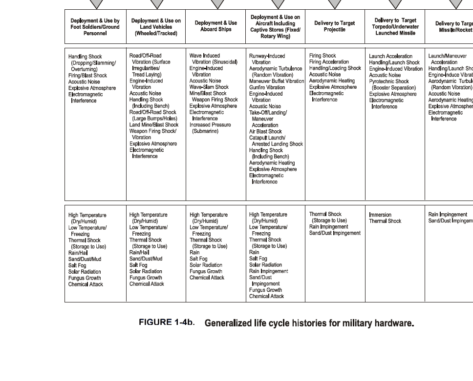
Figure description:
Generalized life cycle histories for military hardware
FIGURE 1-4b. Generalized life cycle histories for military hardware.
| Deployment & Use by Foot Soldiers/Ground Personnel | Deployment & Use on Land Vehicles (Wheeled/Tracked) | Deployment & Use Aboard Ships | Deployment & Use on Aircraft Including Captive Stores (Fixed/Rotary Wing) | Delivery to Target Projectile | Delivery to Target Torpedo/Underwater Launched Missile | Delivery to Target Missile/Rocket |
|---|---|---|---|---|---|---|
| Mechanical / Dynamic Stressors | ||||||
| Handling Shock (Dropping/Slamming/Overturning) | Road/Off-Road Vibration (Surface Irregularities/Tread Laying) | Wave Induced Vibration (Sinusoidal) | Runway-Induced Vibration | Firing Shock | Launch Acceleration | Launch/Maneuver Acceleration |
| Firing/Blast Shock | Engine-Induced Vibration | Engine-Induced Vibration | Aerodynamic Turbulence (Random Vibration) | Firing Acceleration | Handling/Launch Shock | Handling/Launch Shock |
| Acoustic Noise | Acoustic Noise | Acoustic Noise | Maneuver Buffet Vibration | Handling/Loading Shock | Engine-Induced Vibration | Engine-Induced Vibration |
| Explosive Atmosphere | Handling Shock (Including Bench) | Wave-Slam Shock | Gunfire Vibration | Acoustic Noise | Acoustic Noise | Aerodynamic Turbulence (Random Vibration) |
| Electromagnetic Interference | Road/Off-Road Shock (Large Bumps/Holes) | Mine/Blast Shock | Engine-Induced Vibration | Aerodynamic Heating | Pyrotechnic Shock (Booster Separation) | Acoustic Noise |
| Land Mine/Blast Shock | Weapon Firing Shock | Acoustic Noise | Explosive Atmosphere | Explosive Atmosphere | Aerodynamic Heating | |
| Weapon Firing Shock/Vibration | Explosive Atmosphere | Take-Off/Landing/Maneuver Acceleration | Electromagnetic Interference | Electromagnetic Interference | Explosive Atmosphere | |
| Explosive Atmosphere | Electromagnetic Interference | Air Blast Shock | Electromagnetic Interference | |||
| Electromagnetic Interference | Increased Pressure (Submarine) | Catapult Launch/Arrested Landing Shock | ||||
| Handling Shock (Including Bench) | ||||||
| Aerodynamic Heating | ||||||
| Explosive Atmosphere | ||||||
| Electromagnetic Interference | ||||||
| Climatic / Chemical Stressors | ||||||
| High Temperature (Dry/Humid) | High Temperature (Dry/Humid) | High Temperature (Dry/Humid) | High Temperature (Dry/Humid) | Thermal Shock (Storage to Use) | Immersion | Rain Impingement |
| Low Temperature/Freezing | Low Temperature/Freezing | Low Temperature/Freezing | Low Temperature/Freezing | Rain Impingement | Thermal Shock | Sand/Dust Impingement |
| Thermal Shock (Storage to Use) | Thermal Shock (Storage to Use) | Thermal Shock (Storage to Use) | Thermal Shock (Storage to Use) | Sand/Dust Impingement | ||
| Rain/Hail | Rain/Hail | Rain | Rain | |||
| Sand/Dust/Mud | Sand/Dust/Mud | Salt Fog | Salt Fog | |||
| Salt Fog | Salt Fog | Solar Radiation | Solar Radiation | |||
| Solar Radiation | Solar Radiation | Fungus Growth | Rain Impingement | |||
| Fungus Growth | Fungus Growth | Chemical Attack | Sand/Dust Impingement | |||
| Chemical Attack | Chemical Attack | Fungus Growth | ||||
| Chemical Attack |
Notes: The table summarizes environmental factors and stressors associated with different military deployment and delivery scenarios.
Note 1:
The environmental stress events experienced by actual hardware may not always occur in the sequence shown in this profile. The generalized profile is intended to be used as a starting point for a tailored life cycle stress analysis and to provide confidence that all potentially significant environmental conditions have been considered.
Note 2:
[Image shows a stylized black silhouette of a person holding a rifle, positioned above a black silhouette of a bird in flight. Below these silhouettes are several horizontal lines, some of which are intersected by vertical gray bars of varying lengths.]
Note 3:
[Image shows a line drawing of a ship with a complex superstructure, possibly a destroyer or frigate, with multiple levels, masts, and what appear to be radar and communication arrays. The ship is depicted in profile, moving from left to right, with a wake indicated by wavy lines behind it. Below the ship, there is a large downward-pointing arrow, suggesting the ship is descending or moving downward. There are also two gray rectangular blocks below the arrow, possibly representing a dock or platform.]
The generalized profile shows only areas of environmental concem and does not attempt show operational use patterns. The relative frequency and duration of storage, shipping, and mission events must be considered in determining life cycle environmental test parameters. It should also be remembered that even one-shot devices (rockets, shells, etc.) must endure combinations and repetitions of all these events before they are ultimately fired.
Note 5:
In the interest of completeness, some environmental stress generating mechanisms have been included for which corresponding tests are not included in this document. Their absence from this document does not imply a lack of importance; they should be given equal consideration in the life cycle stress analysis.
PART ONE