513.8-2 FAILURE DETECTION PROBLEMS
During a centrifuge test, the detection and analysis of the cause of failure may be difficult. For example, during a centrifuge test, an electronic circuit in a test item might fail due to a capacitor short. This failure might have occurred regardless of the test, or might have been a direct result of the test. Other possibilities exist and a conclusion that the capacitor failed as a result of the test is extremely uncertain without additional evidence. Careful technical consideration must be given to the cause and effect relationship of each failure to prevent erroneous conclusions and unnecessary redesign efforts. There is no definite procedure for failure investigation or troubleshooting; except that drawings, system specification documents, operating instructions, and good engineering practices should be used. Failure may be classified as intermittent, catastrophic, or fatigue. An intermittent failure is one that occurs during the test, but disappears when the test item returns to normal operation after the causative influence is removed. Catastrophic or fatigue failure is one that results in the structural failure of a component of the test item, and can be detected by inspection of instrumentation after the test is concluded.
2.1 Selecting the Acceleration Method
After examining requirements documents and applying the tailoring process in Part One of this Standard to determine where acceleration effects are foreseen in the life cycle of the materiel, use the following to confirm the need for this Method and to place it in sequence with other methods.
MIL-STD-810H
METHOD 513.8
2.1.1 Effects of Acceleration
Acceleration results in loads on mounting hardware and internal loads within materiel. Note that all elements of the materiel are loaded, including fluids. The following is a partial list of detrimental effects from high levels of acceleration. If there is expectation that any of these may occur, it confirms the need to test for this effect.
- a. Structural deflections that interfere with materiel operation.
- b. Permanent deformation, structural cracks, and fractures that disable or destroy materiel.
- c. Broken fasteners and supports that result in loose parts within materiel.
- d. Broken mounting hardware that results in loose materiel within a platform.
- e. Electronic circuit boards that short out and circuits that open up.
- f. Inductances and capacitances that change value.
- g. Relays that open or close.
- h. Actuators and other mechanisms that bind.
- i. Seals that leak.
- j. Pressure and flow regulators that change value.
- k. Pumps that cavitate.
- l. Spools in servo valves that are displaced causing erratic and dangerous control system response.
2.1.2 Sequence Among Other Methods
- a. General. See Part One, paragraph 5.5.
b. Unique to this Method. Examine the life cycle environmental profile to determine the test sequence. Normally, acceleration is experienced after logistic storage and transportation environments and often near the end of the life cycle. Shock, vibration, and thermal stressing prior to acceleration testing is recommended as this will uncover failures that would not occur with unstressed items.
2.2 Selecting a Procedure
This Method includes three test procedures.
- a. Procedure I - Structural Test.
- b. Procedure II - Operational Test.
- c. Procedure III - Crash Hazard Acceleration Test.
- d. Procedure IV - Strength Test.
2.2.1 Procedure Selection Considerations
Subject materiel to be tested to both Procedures I and II tests unless otherwise specified. Subject manned aircraft materiel that is located in occupied areas or in egress and ingress routes to Procedure III. Procedure IV is special case for strength testing materiel that cannot be assessed by Procedures I and II.
2.2.2 Difference Among Procedures
2.2.2.1 Procedure I - Structural Test
Procedure I is used to demonstrate that materiel will structurally withstand the loads induced by in-service accelerations.
2.2.2.2 Procedure II - Operational Test
Procedure II is used to demonstrate that materiel will operate without degradation during and after being subjected to loads induced by in-service acceleration. Rationale for operational test levels can be found in paragaraph 6.1, reference k.
MIL-STD-810H
METHOD 513.8
2.2.2.3 Procedure III - Crash Hazard Acceleration Test
Procedure III is used to disclose structural failures of materiel that may present a hazard to personnel during or after a crash. This test is intended to verify that materiel mounting and/or restraining devices will not fail and that sub- elements are not ejected during a crash. Use for materiel mounted in flight occupied areas and/or that could block aircrew/passenger egress or rescue personnel ingress after a crash. The crash hazard can be evaluated by a static acceleration test (Method 513.8, Procedure III) and/or transient shock (Method 516.8, Procedure V). The requirement for one or both procedures must be evaluated based on the test item.
Only when the system and/or attachment method has a natural frequency below the knee frequency of the shock SRS, might this test be required to supplement the Crash Hazard Shock Test (see Method 516.8, Figure 516.8-9). For planning purposes, Procedure III should be included for budgeting and scheduling consideration until it is shown by analysis or a laboratory test that this procedure isn’t required.
2.2.2.4 Procedure IV – Strength Test
Procedure IV is a strength test primarily intended to generate specific loads in primary structures using sine burst testing. This method may be used as an alternative to static pull or centrifuge testing and is suitable for testing relatively stiff components, electronics boxes, instruments, or space vehicles. The sine burst test is a base-driven test in which the test article is subjected to a few cycles (typically 2 to 10 at peak amplitude) of sinusoidal input. This is usually done below the first resonant frequency of the test article to expose the hardware to a quasi-static loading. An example test profile is shown in Figure 513.8-1.
2.3 Determine Test Levels and Conditions
The tests vary in acceleration level, axis of acceleration, duration, test apparatus, and on/off state of test item. Obtain acceleration values for individual materiel items from the platform structural loads analyses. When the applicable platform is unknown, the values of Tables 513.8-I, 513.8-II, 513.8-III and 513.8-IV and the following paragraphs may be used as preliminary test criteria pending definition of actual installation criteria.
2.3.1 Test Axes
For the purpose of these tests, the axes should be consistent with the sign convention and axes used in the structural analysis of the platform with the direction of forward acceleration of the platform. The test item is tested in each direction along three mutually perpendicular axes for each test procedure. One axis is aligned with the forward acceleration of the platform (fore and aft, X), one axis is aligned with the span-wise direction of the platform (lateral, Y), and the third axis is perpendicular to the plane of the other two axes (up and down, Z). Positive rotational axes and accelerations vary between platforms as they are typically determined by various means such as use of the “left hand” or “right hand rule.” Figure 513.8-2 shows a typical vehicle acceleration axes system with sign convention defined by the “right hand rule”.
2.3.2 Test Levels and Conditions - General
Tables 513.8-I, 513.8-II, and 513.8-III & IV list test levels for Procedure I (Structural Test), Procedure II (Operational Test), and Procedure III (Crash Hazard Acceleration Test), respectively. When the orientation of the materiel item relative to the operational platform is unknown, the highest pertinent level applies to all test axes.
|
MIL-STD-810H
METHOD 513.8
| Vehicle Category 1/ | Forward Acceleration A (g's) 2/ | Test Level | ||||||
|---|---|---|---|---|---|---|---|---|
| Direction of Vehicle Acceleration (See Figure 513.8-2) | ||||||||
| Fore | Aft | Up | Down | Lateral | ||||
| Left | Right | |||||||
| Aircraft 3/, 4/ | 2.0 | 1.5A | 4.5A | 6.75A | 2.25A | 3.0A | 3.0A | |
| Helicopters | 5/ | 4.0 | 4.0 | 10.5 | 4.5 | 6.0 | 6.0 | |
| Manned Aerospace Vehicles 6/ | 6.0 to 12.0 7/ | 1.5A | 0.5A | 2.25A | 0.75A | 1.0A | 1.0A | |
| Aircraft Stores Carried on: | Wing/ Sponson | 2.0 | 7.5A | 7.5A | 9.0A | 4.9A | 5.6A | 5.6A |
| Wing Tip | 2.0 | 7.5A | 7.5A | 11.6A | 6.75A | 6.75A | 6.75A | |
| Fuselage | 2.0 | 5.25A | 6.0A | 6.75A | 4.1A | 2.25A | 2.25A | |
| Ground-Launched Missiles | 8/, 9/ | 1.2A | 0.5A | 1.2A' 10/ | 1.2A' 10/ | 1.2A' 10/ | 1.2A' 10/ | |
1/ Use levels specified for individual platforms and locations on/in the platforms. Use the values of this table only if platform criteria are unavailable.
2 Use levels in this column when forward acceleration is unknown. When the forward acceleration of the vehicle is known, use that value for A.
³ For carrier-based aircraft, use 4 as a minimum value for A, representing a basic condition associated with catapult launches.
4/ For attack and fighter aircraft, add pitch, yaw and roll accelerations as applicable (see paragraph 2.3.3).
For helicopters, forward acceleration is unrelated to acceleration in other directions. Test levels are based on current and near future helicopter design requirements.
6/ Manned vehicles capable of flight in the Earth's atmosphere and surrounding space environment.
When forward acceleration is not known, use the high value of the acceleration range.
8/ A is derived from the propulsion thrust curve data for maximum firing temperature.
2/ In some cases, the maximum maneuver acceleration and the maximum longitudinal acceleration will occur at the same time. When this occurs, test the materiel with the appropriate factors using the orientation and levels for the maximum (vertical) acceleration.
Where is the maximum maneuver acceleration.
MIL-STD-810H
METHOD 513.8
| Vehicle Category 1/ | Forward Acceleration A (g's) 2/ | Test Level | ||||||
|---|---|---|---|---|---|---|---|---|
| Direction of Vehicle Acceleration (See Figure 513.8-2) | ||||||||
| Fore | Aft | Up | Down | Lateral | ||||
| Left | Right | |||||||
| Aircraft 3/,4/ | 2.0 | 1.0A | 3.0A | 4.5A | 1.5A | 2.0A | 2.0A | |
| Helicopters | 5/ 2.0 | 2.0 | 2.0 | 7.0 | 3.0 | 4.0 | 4.0 | |
| Manned Aerospace Vehicles 6/ | 6.0 to 12.0 7/ | 1.0A | 0.33A | 1.5A | 0.5A | 0.66A | 0.66A | |
| Aircraft Stores Carried on: | Wing/ Sponson | 2.0 | 5.0A | 5.0A | 6.0A | 3.25A | 3.75A | 3.75A |
| Wing Tip | 2.0 | 5.0A | 5.0A | 7.75A | 4.5A | 4.5A | 4.5A | |
| Fuselage | 2.0 | 3.5A | 4.0A | 4.5A | 2.7A | 1.5A | 1.5A | |
| Ground-Launched Missiles | 8/,9/ | 1.1A | 0.33A | 1.1A' 10/ | 1.1A' 10/ | 1.1A' 10/ | 1.1A' 10/ | |
1/ Use levels specified for individual platforms and locations on/in the platforms. Use the values of this table only if platform criteria are unavailable.
2 Use levels in this column when forward acceleration is unknown. When the forward acceleration of the vehicle is known, use that value for A.
³ For carrier-based aircraft, use 4 as a minimum value for A, representing a basic condition associated with catapult launches.
4/ For attack and fighter aircraft, add pitch, yaw and roll accelerations as applicable (see paragraph 2.3.3).
For helicopters, forward acceleration is unrelated to acceleration in other directions. Test levels are based on current and near future helicopter design requirements.
6 Manned vehicles capable of flight in the Earth's atmosphere and surrounding space environment.
7/ When forward acceleration is not known, use the high value of the acceleration range.
8/ A is derived from the propulsion thrust curve data for maximum firing temperature.
2' In some cases, the maximum maneuver acceleration and the maximum longitudinal acceleration will occur at the same time. When this occurs, test the materiel with the appropriate factors using the orientation and levels for the maximum (vertical) acceleration.
10/ Where A' is the maximum maneuver acceleration.
| Vehicle/Category | Test Level (g's) ¹ | |||||
|---|---|---|---|---|---|---|
| Direction of Vehicle Acceleration (See Figure 513.8-2) | ||||||
| Fore | Aft | Up | Down | Left | Right | |
| All manned air vehicles except cargo/transport | ||||||
| Personnel capsule | 40 | 12 | 10 | 25 | 14 | 14 |
| Ejection seat | 40 | 7 | 10 | 25 | 14 | 14 |
| All other items 2/ | 40 | 20 | 10 | 20 | 14 | 14 |
| Helicopters 4/ | 20 | 20 | 10 | 20 | 18 | 18 |
| Cargo/transport | ||||||
| Pilot and aircrew seats | 16 | 6 | 7.5 | 16 | 5.5 | 5.5 |
| Passenger seats | 16 | 3 | 4 | 16 | 5.5 | 5.5 |
| Side facing troop seats | 3 | 3 | 5 | 16 | 3 | 3 |
| Personnel restraint | 10 | 5 | 5 | 10 | 3 | 3 |
| Stowable troop seats | 10 | 5 | 5 | 10 | 10 | 10 |
| All other items 2/ | 20 | 10 | 10 | 20 | 10 | 10 |
| Helicopters 4/ | 20 | 20 | 10 | 20 | 18 | 18 |
1/ Use levels specified for individual platforms and locations on/in the platforms. Use the values of this table only if platform criteria are unavailable.
2 The intent of this test is to disclose structural failures of materiel that may present a hazard to personnel during or after a crash. This test is intended to verify that materiel mounting and/or restraining devices will not fail and that sub-elements are not ejected during a crash. Use for materiel mounted in flight occupied areas and/or that could block aircrew/passenger egress or rescue personnel ingress after a crash.
- Test item function is not required following this test. Thus test items that are not suitable for other tests or field use may be used for this test. Ensure test items are structurally representative (strength, stiffness, mass, and inertia) of the production design, but need not be functional. All contents (including fluids) designed to be carried in/on the materiel should be included. Tactical restraint systems should be loaded with the maximum expected weight.
See paragraph 6.1, reference a. Some system specific crash hazard acceleration levels are provided in Table 513.8-IV.
MIL-STD-810H
METHOD 513.8
| AH-64 A & D Aircraft Crash Test Levels (g's) 1 | |||||
|---|---|---|---|---|---|
| Direction of Vehicle Acceleration | Applied Separately | Applied Simultaneously6 | Transport Acceleration Applied Separately (items not able to reach cockpit) | ||
| Up | 20 | 10 | 20 | 10 | 4.5 |
| Down | 10 | 5 | 10 | 5 | 2 |
| Lateral | ±20 | ±10 | ±10 | ±20 | 1.5 |
| Forward | 20 | 20 | 10 | 10 | 1.5 |
| Aft | 20 | 20 | 10 | 10 | 3 |
OH-58D Kiowa Warrior Aircraft Crash Test Levels (g's) (Applied Separately) ²/
| Direction of Vehicle Acceleration | Seat (200 lb per) | Cargo Equipment (items that can get into cockpit)6/ | Equipment Mounted in Aft Equipment Compartment | |
|---|---|---|---|---|
| Up | 20 | 16 | 8 | |
| Down | 10 | 8 | 4 | |
| Lateral | 20 | 16 | 8 | |
| Forward | 10 | 8 | 4 | |
| Aft | 10 | 16 | 8 | |
CH-47D/F Aircraft Crash Test Levels (g's)
| Direction of Vehicle Acceleration | Applied Separately | (g) | ||
|---|---|---|---|---|
| Up | - | |||
| Down | 8 | |||
| Lateral | 8 | |||
| Forward | 8 | |||
| Aft | - |
UH-1H Aircraft Crash Test Levels (g's)
| Direction of Vehicle Acceleration | Applied Separately | |||
|---|---|---|---|---|
| Up | 8 | |||
| Down | 4 | |||
| Lateral | ±8 | |||
| Forward | 8 | |||
| Aft | - |
UH/HH/MH-60A/L/M Aircraft Crash Test Levels (g's)
| Direction of Vehicle Acceleration | Applied Separately | Applied Simultaneously 6/ | External 6/ (in any combination) | ||
|---|---|---|---|---|---|
| Up | 20 | 10 | 20 | 10 | 6 |
| Down | 10 | 5 | 10 | 5 | 3 |
| Lateral | ±18 | ±9 | ±9 | ±18 | 3 (in) / 6 (out) |
| Forward | 20 | 20 | 10 | 10 | 6 |
| Aft | 20 | 20 | 10 | 10 | - |
| 1/ See Design Criteria Report, Report No. 77-Y-8001-3 paragraph 6.1, reference b. |
| 2/ See System Specification, Specification No. 406-947-500B paragraph 6.1, reference c. |
| 3/ See reference Structural Design Criteria, Document No. 145-SS-603 paragraph 6.1, reference d. |
| 4/ See reference System Specification, Contract DAAJ01-74-C-0175 paragraph 6.1, reference e. |
| 5/ See reference Aircraft Specification, Document No. SES-700700 paragraph 6.1, reference f. |
| 6/ Apply the worst case combination of test levels simultaneously. The requirement to test in different directions simultaneously can be accomplished through angled fixtures. |
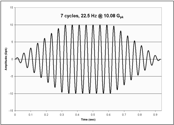
Figure description:
7 cycles, 22.5 Hz @ 10.08 Gpk
7 cycles, 22.5 Hz @ 10.08 Gpk
| Time (sec) | Amplitude (Gpk) |
|---|---|
| 0.000 | 0.0 |
| 0.011 | 0.5 |
| 0.022 | 0.0 |
| 0.033 | -1.1 |
| 0.044 | 0.0 |
| 0.056 | 1.8 |
| 0.067 | 0.0 |
| 0.078 | -2.5 |
| 0.089 | 0.0 |
| 0.100 | 3.3 |
| 0.111 | 0.0 |
| 0.122 | -4.0 |
| 0.133 | 0.0 |
| 0.144 | 4.6 |
| 0.156 | 0.0 |
| 0.167 | -5.4 |
| 0.178 | 0.0 |
| 0.189 | 6.1 |
| 0.200 | 0.0 |
| 0.211 | -6.9 |
| 0.222 | 0.0 |
| 0.233 | 7.8 |
| 0.244 | 0.0 |
| 0.256 | -8.4 |
| 0.267 | 0.0 |
| 0.278 | 8.9 |
| 0.289 | 0.0 |
| 0.300 | -9.6 |
| 0.311 | 0.0 |
| 0.322 | 10.0 |
| 0.333 | 0.0 |
| 0.344 | -10.0 |
| 0.356 | 0.0 |
| 0.367 | 10.0 |
| 0.378 | 0.0 |
| 0.389 | -10.0 |
| 0.400 | 0.0 |
| 0.411 | 10.0 |
| 0.422 | 0.0 |
| 0.433 | -10.0 |
| 0.444 | 0.0 |
| 0.456 | 10.0 |
| 0.467 | 0.0 |
| 0.478 | -10.0 |
| 0.489 | 0.0 |
| 0.500 | 10.0 |
| 0.511 | 0.0 |
| 0.522 | -10.0 |
| 0.533 | 0.0 |
| 0.544 | 10.0 |
| 0.556 | 0.0 |
| 0.567 | -10.0 |
| 0.578 | 0.0 |
| 0.589 | 10.0 |
| 0.600 | 0.0 |
| 0.611 | -10.0 |
| 0.622 | 0.0 |
| 0.633 | 9.8 |
| 0.644 | 0.0 |
| 0.656 | -9.1 |
| 0.667 | 0.0 |
| 0.678 | 8.4 |
| 0.689 | 0.0 |
| 0.700 | -7.6 |
| 0.711 | 0.0 |
| 0.722 | 6.8 |
| 0.733 | 0.0 |
| 0.744 | -6.1 |
| 0.756 | 0.0 |
| 0.767 | 5.4 |
| 0.778 | 0.0 |
| 0.789 | -4.6 |
| 0.800 | 0.0 |
| 0.811 | 3.8 |
| 0.822 | 0.0 |
| 0.833 | -3.0 |
| 0.844 | 0.0 |
| 0.856 | 2.2 |
| 0.867 | 0.0 |
| 0.878 | -1.5 |
| 0.889 | 0.0 |
| 0.900 | 0.8 |
| 0.911 | 0.0 |
| 0.922 | -0.4 |
| 0.933 | 0.0 |
Notes: The chart shows an amplitude-modulated sine wave with a 22.5 Hz frequency, featuring 7 full-amplitude cycles at approximately 10.08 Gpk. The signal ramps up from 0 to 0.32 seconds and ramps down from 0.63 to 0.94 seconds.
Figure 513.8-1. Example sine burst test specification for strength testing (from NASA-HDBK-7008).
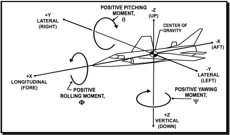
Figure description:
The image illustrates the standard coordinate system and rotational moments for an aircraft, centered on its Center of Gravity.
Linear Axes:
- X-Axis (Longitudinal: +X is Fore, -X is Aft.
- Y-Axis (Lateral: +Y is Right, -Y is Left.
- Z-Axis (Vertical: +Z is Down, -Z is Up.
Rotational Moments:
- Rolling Moment (Φ: Rotation around the X-axis.
- Pitching Moment (θ: Rotation around the Y-axis.
- Yawing Moment (Ψ: Rotation around the Z-axis.
Figure 513.8-2. Typical directions of vehicle acceleration (right hand rule).
2.3.3 Test Levels and Conditions - Fighter and Attack Aircraft
The test levels as determined from Tables 513.8-I and 513.8-II are based on accelerations at the center of gravity (CG) of the platform. For fighter and attack aircraft, the test levels, must be increased for materiel that is located away from the vehicle CG to account for loads induced by roll, pitch, and yaw during maneuvers. When criteria are developed for specific aircraft, maneuver cases are considered and the resulting additional angular accelerations may add or subtract effects from the linear acceleration effects. When the following relationships (a-f) are used, it must be
assumed that the load factors always add. Thus absolute values are used in the equations. Add the load factors derived below to the Operational Test (Procedure II) levels of Table 513.8-II. Multiply the load factors derived below by 1.5 and add to the Structural Test (Procedure I) levels of Table 513.8-I. Do not add these values to the Crash Hazard Acceleration Test (Procedure III) levels of Tables 513.8-III and 513.8-IV.
a. Roll maneuver, up and down test direction. The additional load factor () induced by roll, is computed as follows:
b. Roll maneuver, lateral left and lateral right directions. The additional load factor (N) induced by roll, is computed as follows: N = (y/g) ( / t) + (z/g) ^{2}$$\phi/ t - c. Pitch maneuver, up and down test directions. The additional load factor (ΔNz) induced by pitch change, is computed as follows: - d. Pitch maneuver, fore and aft test directions. The additional load factor (ΔNx) induced by pitch change, is computed as follows:- e. Yaw maneuver, lateral left and right test directions. The additional load factor induced by yaw, is computed as follows:- f. Yaw maneuver, fore and aft test directions. The additional load factor (ΔNx) induced by yaw change, is computed as follows:
where:
x = fore and aft distance of materiel from the aircraft CG, m (in.) y = lateral distance of materiel from the aircraft CG, m (in.) z = vertical distance of materiel from the aircraft CG, m (in.) g = acceleration of gravity, 9.81 m/sec² (386 in/sec²) ϕ = angle of rotation about the X axis (roll), rad d ϕ/d t = maximum roll velocity in rad/sec (if unknown use 5 rad/sec) d ²ϕ/d t² = maximum roll acceleration in rad/sec² (if unknown use 20 rad/sec²) θ = angle of rotation about the Y axis (pitch), rad d θ/d t = maximum pitch velocity in rad/sec (if unknown use 2.5 rad/sec) d ²θ/d t² = maximum pitch acceleration in rad/sec² (if unknown use 5 rad/sec²) ψ = angle of rotation about the Z axis (yaw), rad d ψ/d t = maximum yaw velocity in rad/sec (if unknown use 4 rad/sec) d ²ψ/d t² = maximum yaw acceleration in rad/sec² (if unknown use 3 rad/sec²)
2.4 Special Considerations
-
a. Sway space measurements. If a piece of materiel is mounted on vibration isolators or shock mounts, perform the tests with the materiel mounted on the isolators/mounts. Measure the deflections of the isolators/mounts while the test item is exposed to the test accelerations. These data are needed to indicate potential interference with adjacent materiel, (i.e., define sway space requirements).
-
b. Acceleration simulation. Careful assessment of the function and characteristics of the test item has to be made in selecting the apparatus on which the acceleration tests are to be performed due to the differences in the manner in which acceleration loads are produced. There are two types of apparatus that are commonly used: the centrifuge and a track/rocket-powered sled combination.
-
c. Centrifuge. The centrifuge generates acceleration loads by rotation about a fixed axis. The direction of acceleration is always radially toward the center of rotation of the centrifuge, whereas the direction of the load induced by acceleration is always radially away from the axis of rotation. When mounted directly on the test arm, the test item experiences both rotational and translational motion. Ensure the centrifuge or turn table is properly balanced. The direction of the acceleration and the load induced is constant with respect to the test item for a given rotational speed, but the test item rotates 360 degrees for each revolution of the arm. Certain centrifuges have counter-rotating fixtures mounted on the test arm to correct for rotation of the test item. With this arrangement, the test item maintains a fixed direction with respect to space, but the direction of the acceleration and the induced load rotates 360 degrees around the test item for each revolution of the arm. Another characteristic is that the acceleration and induced load are in direct proportion to the distance from the center of rotation. This necessitates the selection of a centrifuge of adequate size so that the portions of the test item nearest to and furthest from the center of rotation are subjected to not less than 90 percent or more than 110 percent, respectively, of the specified test level. Further information regarding centrifuge testing may be found in paragraph 6.1, reference g.
-
d. Track/rocket-powered sled. The track/rocket-powered sled test arrangement generates linear acceleration in the direction of the sled acceleration. The test item mounted on the sled is uniformly subjected to the same acceleration level that the sled experiences. The acceleration test level and the time duration at the test level is dependent upon the length of the track, the power of the rocket, and the rocket charge. The sled track generally will produce a significant vibration environment due to track roughness. Typically this vibration is significantly more severe than the normal in-service use environment. Careful attention to the attachment design may be needed to isolate the test item from this vibration environment. In performing Procedure II tests, the support equipment necessary to operate the test item is mounted on the sled and traverses the track with the test item. This requires the use of self-contained power units and a remote control system to operate the test item while traversing the track. Telemetering or ruggedized instrumentation is required to measure the performance of the test item while it is exposed to the test load. Further information regarding rocket sled testing may be found in paragraph 6.1, reference h.
-
e. Sine burst testing. This method allows strength testing to be conveniently performed as part of a planned dynamic test sequence. Test schedule efficiency is improved because the test item can remain installed on the shaker table after a vibration test eliminating tear down, transport, and setup times at another facility. Note, it is important that all parties involved fully understand the risks and limitations of this approach. Possible test item damage may be caused by: shaker displacement limitations; open loop shaker control; and depending upon the level of test item assembly there may be unexpected amplification of component resonances in the hardware. Further information regarding this method may found in paragraph 6.1, reference i.