4.1 Test Facility
The required apparatus consists of a chamber or cabinet, together with auxiliary instrumentation, capable of establishing, maintaining and monitoring (see Part One, paragraph 5.18) the specified test conditions. Use a chamber with a means of determining the explosiveness of a sample of the mixture, such as a spark gap or glow plug ignition source with sufficient energy to ignite a 3.82 percent hexane mixture. An alternative method of determining the explosive characteristics of the vapor is by using a calibrated explosive gas meter that verifies the degree of explosiveness and the concentration of the fuel-air mixture. Chamber air temperature is typically controlled by indirect heating such as heated chamber walls. Due to varying geographic facility locations and differences in site pressure, it is highly recommended that the chamber has the capability to reach 1000 ft (14.17 psia) or below for the low altitude portion of the test. The minimum ignition energy varies inversely with the square of the pressure. Due to the change in ignition energy between sea level (14.7 psia) and 7,000 ft (11.3 psia) it is possible for the equipment under test to
pass at 11.3 psia, whereas it may have failed if tested at pressures nearer 14.7 psia. The minimum ignition energy at 1000 ft (14.17 psia) is within 5 percent of the optimum at sea level.
4.2 Controls
Before each test, verify the critical parameters. Ensure spark devices function properly and the fuel atomizing system is free from deposits that could inhibit proper functioning. Adjust the empty test chamber to the highest test altitude, shut off the vacuum system and measure the rate of any air leakage. Verify that any leakage is not sufficient to prevent the test from being performed as required, i.e., introduce the test fuel and wait three minutes for full vaporization, yet still be at least 1000 m above the test altitude.
4.3 Test Interruption
Test interruptions can result from two or more situations, one being from failure or malfunction of test chambers or associated test laboratory equipment. The second type of test interruption results from failure or malfunction of the test item itself during required or optional performance checks.
4.3.1 Test Interruption Due To Chamber Malfunction
- a. General. See Part One, paragraph 5.11 of this Standard.
- b. Specific to this Method. If there is an unscheduled undertest interruption, restore the chamber air pressure to ground ambient pressure and purge the chamber to remove the flammable atmosphere. Achieve the required test altitude, inject the required volume of n-hexane and reinitiate the test using the same test item.
4.3.2 Test Interruption Due To Test item Operation Failure
Failure of the test item(s) to function as required during mandatory or optional performance checks during testing presents a situation with several possible options.
- a. The preferable option is to replace the test item with a “new” one and restart from Step 1.
- b. A second option is to replace / repair the failed or non-functioning component or assembly with one that functions as intended, and restart the entire test from Step 1.
NOTE: When evaluating failure interruptions, consider prior testing on the same test item and consequences of such.
4.4 Test Setup
- a. General. See Part One, paragraph 5.8.
- b. Unique to this Method. For test item thermal stabilization measurements for both procedures, install thermocouples on the most massive functional part of the test item, and two thermocouples attached to the inside the of test chamber to detect any temperature increase due to burning of the mixture.
4.5 Test Execution
The following steps, alone or in combination, provide the basis for collecting necessary information concerning the materiel in an explosive atmosphere.
4.5.1 Preparation for Test
Before starting the test, review pretest information in the test plan to determine test details (e.g., procedures, test item configuration, test temperature, test altitude, etc.).
- a. Procedure I - Operation in an Explosive Atmosphere.
- (1) Install the test item in the test chamber in such a manner that it may be operated and controlled from the exterior of the chamber via sealed cable ports. Unless permanently sealed (not to be opened for maintenance or other purposes), remove or loosen the external covers of the test item to facilitate the penetration of the explosive mixture. Test items requiring connection between two or more units may,
because of size limitations, have to be tested independently. In this case, extend any interconnections through the cable ports.
- (2) Operate the test item to verify correct remote operation. If possible, identify the location of any sparking components that could cause an explosion. If required, conduct a thermal survey to determine the temperature of components or areas/surfaces that may be potential hot spots. If the test item operates satisfactorily, proceed to paragraph 4.5.2 or 4.5.3 as appropriate. If not, resolve the problems and repeat this Step.
- (3) When necessary, simulate in-service mechanical loads on drive assemblies and servo-mechanical systems, and electrical loads on switches and relays; duplicate torque, voltage, current, inductive reactance, etc. In all instances, operate the test item in a manner representative of service use.
- b. Procedure II - Explosion Containment.
- (1) Make provision to circulate the fuel-air mixture into the case being tested. In the case of forced-air-cooled materiel, the cooling air must contain the proper fuel-air mixture. For materiel not using forced-air cooling, drill and tap the case for insertion of a hose from a blower (to insert the fuel-air mixture), as well as for an outlet hose connection. Take adequate precautions to prevent ignition of the ambient mixture by backfire or release of pressure through the supply or vent hose. Do not alter the case internal volume by more than ± 5 percent with any modification to facilitate the introduction of ignitable vapor.
- (2) Provide a positive means of igniting the explosive mixture within the case. Drill or tap the case as necessary for a spark gap, or mount a spark gap internally. Ensure points of ignition are not be more that 1.27 cm (0.5 inch) from any vent holes or flame arresting devices; and, unless the design of the materiel makes this impractical, use as many points of ignition as are practical.
- (3) To detect explosions within the case, insert a thermocouple into the case, and attach it to a sensitive galvanometer outside the test chamber.
- (4) Ensure the air within the test chamber has a water vapor dew point lower than 10 °C (50 °F) per paragraph 2.2.4.
4.5.2 Procedure I - Operation in an Explosive Atmosphere
- Step 1 Figure 511.7-2 contains a visual representation of typical test conduct. Test altitudes should be tailored to the individual item requirements. With the test item installed, seal the chamber and stabilize the test item and chamber air temperature to the high operating temperature of the test item (±2 °C (±3.6 °F)) for a minimum duration of one hour. Monitor the chamber wall temperature and chamber air temperature throughout the duration of test to ensure uniform heating. Excessive chamber wall temperature could adversely affect the test item.
- Step 2 Adjust the chamber air pressure to simulate the highest operating altitude of the test item (not to exceed 12,200 m (40,000 ft)) plus 2000 m (6600 ft) to allow for introducing, vaporizing, and mixing the fuel with the air as described in paragraph 2.2.2.
- Step 3 Slowly introduce the required volume of n-hexane into the test chamber and begin reducing the simulated altitude at a rate no faster than 100 m (330 ft) per minute.
- Step 4 Circulate the test atmosphere and continue to reduce the simulated chamber altitude for at least three minutes to allow for complete vaporization of fuel and the development of a homogeneous mixture, and for the chamber pressure to reach the test altitude.
- Step 5 At a pressure equivalent to 1000 m (3300 ft) above the test altitude, verify the potential explosiveness of the fuel-air vapor by attempting to ignite a sample of the mixture taken from the test chamber using a spark-gap device or glow plug ignition source with sufficient energy to ignite a 3.82 percent hexane mixture. If ignition does not occur, purge the chamber of the fuel vapor and repeat Steps 1-4. An alternative method of determining the explosive characteristics of the vapor is by using a calibrated explosive gas meter that verifies the degree of explosiveness and the concentration of the fuel-air mixture.
| Step 6 | Although above the maximum operational altitude of the test item, attempt to operate the test item, making and breaking electrical contacts, such as switches, mechanical relays, and connectors as often as possible for minimum of three power/operational cycles. Continue operation from this step until completion of Step 8. Note the altitude at which the test item begins proper operation. If the test item fails to operate as intended, follow the guidance in paragraph 4.3.2 for test item failure. |
| Step 7 | To ensure adequate mixing of the fuel and air, slowly decrease the simulated chamber altitude at a rate no faster than 100 m (330 ft) per minute by bleeding air into the chamber. |
| Step 8 | Stop decreasing the altitude at 1000 m (3300 ft) below the test altitude or at ground level, whichever is reached first, and perform an operational check, and switch off power to the test item. If the test item fails to operate as intended, follow the guidance in paragraph 4.3.2 for test item failure. |
| Step 9 | Verify the potential explosiveness of the air-vapor mixture as in Step 5 above. If ignition does not occur, purge the chamber of the fuel vapor, and repeat the test from Step 1. |
| Step 10 | Adjust the simulated chamber altitude to the equivalent of 2000 m (6600 ft) above site pressure. |
| Step 11 | Slowly introduce the required volume of n-hexane into the test chamber and begin reducing the simulated altitude at a rate no faster than 100 m (330 ft) per minute. (Note: In calculating the fuel volume to be added, providing the chamber has not been purged, subtract the volume introduced in Step 3 to maintain the proper fuel-air mixture.). |
| Step 12 | Circulate the test atmosphere for at least three minutes to allow for complete vaporization of fuel and the development of a homogeneous mixture, and for the chamber pressure to reach the test altitude. |
| Step 13 | At a pressure equivalent to 1000 m (3300 ft) above the site pressure, verify the potential explosiveness of the fuel-air vapor by attempting to ignite a sample of the mixture taken from the test chamber using a spark-gap device or glow plug ignition source with sufficient energy to ignite a 3.82 percent hexane mixture. If ignition does not occur, purge the chamber of the fuel vapor and repeat Steps 10-13. An alternative method of determining the explosive characteristics of the vapor is by using a calibrated explosive gas meter that verifies the degree of explosiveness and the concentration of the fuel-air mixture. |
| Step 14 | Attempt to operate the test item and continue operation from this step until completion of Step 16. Make and break electrical contacts, such as switches, mechanical relays, and connectors as often as possible for minimum of three power/operational cycles. Note whether the test item resumes proper operation. If the test item fails to operate as intended, follow the guidance in paragraph 4.3.2 for test item failure. |
| Step 15 | To ensure adequate mixing of the fuel and air, slowly decrease the simulated chamber altitude at a rate no faster than 100 m (330 ft) per minute by bleeding air into the chamber. |
| Step 16 | At site pressure, perform one last operational check and switch-off power to the test item. If required, ensure the test item temperature has stabilized (in accordance with Part One paragraph 5.4.1) prior to conducting the final operational check. |
| Step 17 | Verify the potential explosiveness of the air-vapor mixture as in Step 5, above. If ignition does not occur, purge the chamber of the fuel vapor, and repeat the test from Step 10. |
| Step 18 | Adjust the chamber to standard ambient conditions and document the test results. See paragraph 5 of this Method for analysis of results. |
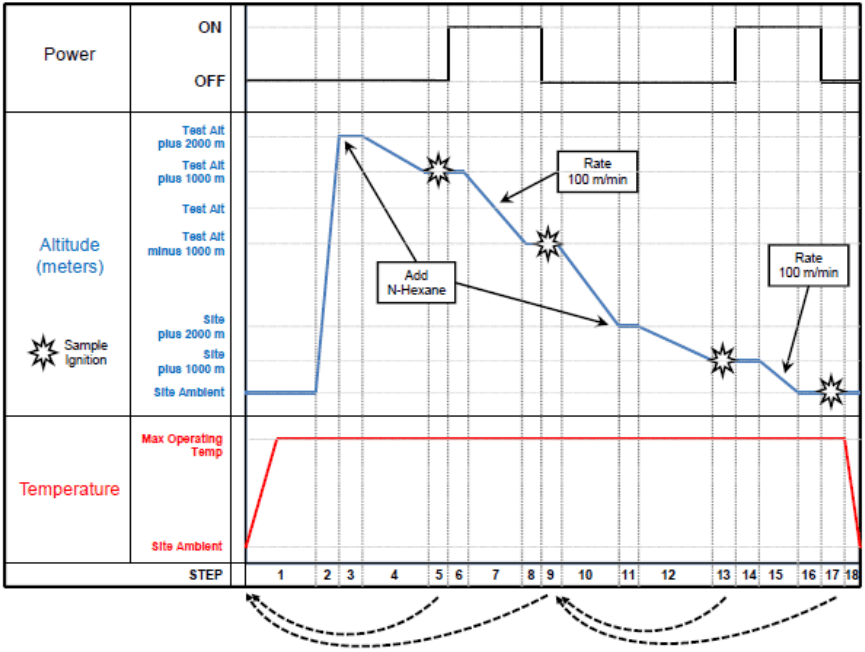
Figure description:
Power, Altitude, and Temperature Profile by Step
Legend
- Sample Ignition — color: Black; symbol: Eight-pointed star
Annotations
- Add N-Hexane (text_label - position: Starts of Step 3 and Step 11)
- Rate 100 m/min (text_label - position: Descent phases in Steps 7-8 and Step 16)
- Cycle Indication Arrows (text_label - position: Bottom of chart linking Steps 1 to 5, 5 to 9, 9 to 13, and 13 to 17)
| STEP | Power | Altitude (meters) | Temperature | Annotations |
|---|---|---|---|---|
| 1 | OFF | Site Ambient | Rising from Site Ambient to Max Operating Temp | |
| 2 | OFF | Site Ambient | Max Operating Temp | |
| 3 | OFF | Climbing from Site Ambient to Test Alt plus 2000 m | Max Operating Temp | Add N-Hexane (start of step) |
| 4 | OFF | Test Alt plus 2000 m | Max Operating Temp | |
| 5 | OFF | Descending from Test Alt plus 2000 m to Test Alt plus 1000 m | Max Operating Temp | Sample Ignition (at end of step) |
| 6 | ON | Test Alt plus 1000 m | Max Operating Temp | |
| 7 | ON | Descending (Rate 100 m/min) | Max Operating Temp | |
| 8 | ON | Descending to Test Alt minus 1000 m | Max Operating Temp | |
| 9 | OFF | Test Alt minus 1000 m | Max Operating Temp | Sample Ignition |
| 10 | OFF | Descending | Max Operating Temp | |
| 11 | OFF | Descending to Site plus 2000 m | Max Operating Temp | Add N-Hexane (start of step) |
| 12 | OFF | Site plus 2000 m | Max Operating Temp | |
| 13 | OFF | Descending from Site plus 2000 m to Site plus 1000 m | Max Operating Temp | Sample Ignition (at end of step) |
| 14 | ON | Site plus 1000 m | Max Operating Temp | |
| 15 | ON | Site plus 1000 m | Max Operating Temp | |
| 16 | ON | Descending to Site Ambient (Rate 100 m/min) | Max Operating Temp | |
| 17 | OFF | Site Ambient | Max Operating Temp | Sample Ignition |
| 18 | OFF | Site Ambient | Falling from Max Operating Temp to Site Ambient |
Notes: The figure illustrates a combined test profile where 'Power' alternates between ON and OFF states, 'Altitude' follows a complex climb and stepped descent pattern, and 'Temperature' is held at 'Max Operating Temp' for the majority of the duration. Steps are demarcated by vertical dashed lines. Specific events like 'Add N-Hexane' and 'Sample Ignition' are triggered at precise points in the sequence.
Figure 511.7-2. Typical representation of Procedure I conduct.
4.5.3 Procedure II - Explosion Containment
- Step 1 Place the test item or a model of the test item of the same volume and configuration within the case, and install the case in the explosion chamber.
- Step 2 Ensure the air within the test chamber has a water vapor dew point lower than 10 °C (50 °F) per paragraph 2.2.4.
- Step 3 Seal the chamber with the test item inside, and raise the chamber air temperature to the high operating temperature of the test item.
- Step 4 When the temperature of the both the test item and the test chamber inner walls come to within 11 °C (20 °F) of the chamber air temperature, reduce the chamber air pressure to 2000 m (6600 ft) of simulated altitude above the site ambient pressure (i.e., ground level).
- Step 5 Slowly introduce the required quantity of n-hexane into the test chamber to obtain an optimum fuel-vapor/air mixture, and then introduce it into the interior of the test item.
- Step 6 Slowly decrease the simulated chamber altitude (no faster than 100 m (330 ft) per minute) to return the pressure altitude to site pressure (i.e., ground level).
- Step 7 Energize the internal case ignition source and confirm the occurrence of an explosion within the test item using the installed thermocouple. If no explosion occurs, purge the chamber and the test item of all air/fuel vapor and return to Step 3.
MIL-STD-810H
METHOD 511.7
- Step 8 If an explosion does occur inside the test item’s case and did not propagate to the fuel/air mixture outside the test item, repeat Steps 4-10 four times if the test item’s case is not in excess of 0.02 times the chamber volume. If the test item volume is equal to or greater than 0.02 times the chamber volume, purge the chamber and test item of air/fuel vapor and repeat Steps 3-10 four times.
- Step 9 Check the potential explosiveness of the air/fuel vapor mixture by attempting to ignite a sample of the mixture by a spark or glow plug. If the chamber sample does not ignite, purge the chamber of all air/fuel vapor mixture, and repeat the entire test from Step 3.
Step 10 Document the test results. See paragraph 5 of this Method for analysis of results.