4.1 Test Facility
Ensure the apparatus used in performing the salt fog test includes the following.
4.1.1 Test Chamber
Use supporting racks that do not affect the characteristics of the salt fog mist. No part of the test setup that contacts the test item may induce electrolytic corrosion. Do not allow condensation to drip on the test item. Do not return any liquid that comes in contact with either the chamber or the test item to the salt solution reservoir. Vent the exposure area to prevent pressure buildup. Ensure the test chamber has a waste collection system so that all waste material can be analyzed prior to disposal. Dispose of any material determined to be hazardous waste in accordance with local, state and federal regulations.
4.1.2 Salt Solution Reservoir
Ensure the salt solution reservoir is made of material that is non-reactive with the salt solution, e.g., glass, hard rubber, or plastic.
4.1.3 Salt Solution Injection System
Filter the salt solution (Figures 509.7-1 and -2) and inject it into the test chamber with atomizers that produce a finely divided, wet, dense fog. Use atomizing nozzles and a piping system made of material that is non-reactive to the salt solution. Do not let salt buildup clog the nozzles. Suitable atomization has been obtained in chambers having a volume of less than 0.34 m³ (12 ft³) under the following conditions:
- a. Nozzle pressure as low as practical to produce fog at the required rate.
- b. Orifices between 0.5 and 0.76 mm (0.02 and 0.03 in.) in diameter.
- c. Atomization of approximately 2.8 liters of salt solution per 0.28 m³ (10 ft³) of chamber volume per 24 hours.
When chambers with a volume considerably in excess of 0.34 m³ (12 ft³) are used, the conditions specified may require modification.
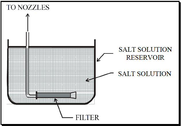
Figure description:
Figure 509.7-1: Location of salt solution filter
Key Components:
- Salt Solution Reservoir: The container holding the liquid.
- Salt Solution: The fluid medium stored within the reservoir.
- Filter: A horizontal cylindrical component submerged at the bottom of the reservoir.
- Outlet Tube: A vertical line connecting the filter to external spray nozzles (labeled "TO NOZZLES".
Function: The diagram illustrates the submerged placement of a filter within a reservoir, ensuring salt solution is filtered before being drawn up and out to the delivery nozzles.
Figure 509.7-1. Location of salt solution filter.
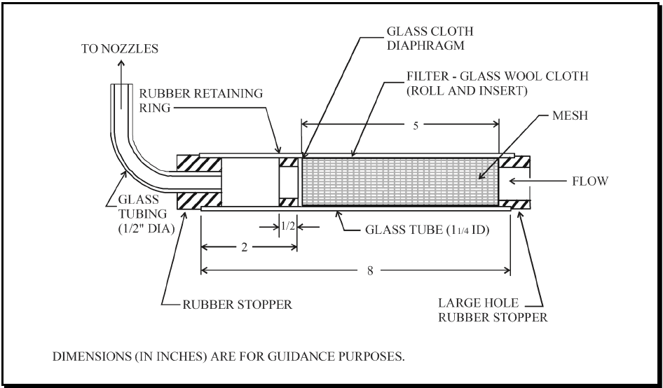
Figure description:
Figure 509.7-2: Salt solution filter
Key Components and Specifications:
- Main Body: Glass tube (1 1/4" ID with a total length of 8 inches.
- Inlet: Flow entering through a "Large hole rubber stopper" on the right.
- Filter Element: 5-inch section containing mesh and a glass wool cloth filter (roll and insert.
- Separation: Glass cloth diaphragm positioned between the filter section and the outlet section.
- Outlet: Glass tubing (1/2" DIA leading "To Nozzles," secured by a rubber stopper and a rubber retaining ring.
- Internal Spacing: 2-inch gap between the outlet stopper and the diaphragm, with a 1/2-inch internal ring/spacer.
- Note: All dimensions are in inches and provided for guidance purposes.
Figure 509.7-2. Salt solution filter.
4.1.4 Salt Fog Collection Receptacles
Suitable collecting devices are glass or plastic funnels each with a diameter of 10 cm (3.94 in.). The funnel stems can be inserted into graduated cylinders (100 ml volume) or crystallizing dishes with same diameter can be used.
4.2 Controls
Preheat the oil-free and dirt-free compressed air used to produce the atomized solution (to offset the cooling effects of expansion to atmospheric pressure) (see Table 509.7-I).
| Air Pressure (kPa) | 83 | 96 | 110 | 124 |
|---|---|---|---|---|
| Preheat temperature (°C) (before atomizing) | 46 | 47 | 48 | 49 |
4.3 Test Interruption
Test interruptions can result from two or more situations, one being from failure or malfunction of test chambers or associated test laboratory equipment. The second type of test interruption results from failure or malfunction of the test item itself during required or optional performance checks.
4.3.1 Interruption Due to Chamber Malfunction
- a. General. See Part One, paragraph 5.11 of this standard.
- b. Specific to this Method.
- (1) Undertest interruption. If an unscheduled test interruption occurs that causes the test conditions to exceed allowable tolerances toward standard ambient conditions, give the test item a complete visual examination and develop a technical evaluation of the impact of the interruption on the test results. Restart the test at the point of interruption and re-stabilize the test item at the test conditions.
MIL-STD-810H
METHOD 509.7
- (2) Overtest interruption. If an unscheduled test interruption occurs that causes the test conditions to exceed allowable tolerances away from standard ambient conditions, stabilize the test conditions to within tolerances and hold them at that level until a complete visual examination and technical evaluation can be made to determine the impact of the interruption on test results. If the visual examination or technical evaluation results in a conclusion that the test interruption did not adversely affect the final test results, or if the effects of the interruption can be nullified with confidence, restabilize the pre-interruption conditions and continue the test from the point where the test tolerances were exceeded.
4.3.2 Interruption Due to Test Item Operation Failure
non2 Interruption Due to Test Item Operation Failure. Failure of the test item(s) to function as required during mandatory or optional performance checks during testing presents a situation with several possible options.
- a. The preferable option is to replace the test item with a “new” one and restart from Step 1.
- b. A second option is to replace / repair the failed or non-functioning component or assembly with one that functions as intended, and restart the entire test from Step 1.
NOTE: When evaluating failure interruptions, consider prior testing on the same test item and consequences of such.
4.4 Test Setup
- a. General. See Part One, paragraph 5.8.
- b. Unique to this Method. Ensure the fallout collection containers are situated in the chamber such that they will not collect fluids dripping from the test item.
4.5 Test Execution
Test Execution The following steps, alone or in combination, provide the basis for collecting necessary information concerning the test item in a salt fog environment.
4.5.1 Preparation for Test
4.5.1.1 Preliminary Steps
Before starting the test, determine the test details (e.g., procedure variations, test item configuration, cycles, durations, parameter levels for storage/operation, etc.) from the test plan. (See paragraph 3.1 above.)
- a. Handling and configuration.
- (1) Handle the test item as little as possible. Prepare the test item for testing immediately before exposure. Unless otherwise specified, ensure the test item surfaces are free of surface contamination such as oil, grease, or dirt that could cause a water break. Do not use corrosive solvents, solvents that deposit either corrosive or protective films, or abrasives other than a paste of pure magnesium oxide in any cleaning methods.
- (2) Configure the test item as specified in the test plan and insert it into the test chamber.
- b. Preparation of salt solution. For this test, use sodium chloride containing (on a dry basis) not more than 0.1 percent sodium iodide and not more than 0.5 percent total impurities. Do not use sodium chloride containing anti-caking agents because such agents may act as corrosion inhibitors. Unless otherwise specified, prepare a 5 ±1 percent solution by dissolving 5 parts by weight of salt in 95 parts by weight of water. Adjust to and maintain the solution at a specific gravity (Figure 509.7-3 and Table 509.7-II) by using the measured temperature and density of the salt solution. If necessary, add sodium tetraborate (borax) to the salt solution as a pH stabilization agent in a ratio not to exceed 0.7g sodium tetraborate to 75 liters of salt solution. Maintain the pH of the salt solution, as collected as fallout in the exposure chamber, between 6.5 and 7.2 with the solution temperature at +35 ±2 °C (95 ±4 °F). To adjust the pH, use only diluted chemically pure hydrochloric acid or chemically pure sodium hydroxide. Make the pH measurement either electrometrically or colorimetrically.
- c. Chamber operation verification. Unless the chamber has been used within five days or the nozzle becomes clogged, immediately before the test and with the exposure chamber empty, adjust all test parameters to those required for the test. Maintain these conditions for at least one 24-hour period or until proper operation and salt fog collection can be verified. To verify the chamber is operating properly, measure the salt fog fallout after 24 hours. Monitor and record the test chamber temperature.
MIL-STD-810H
METHOD 509.7
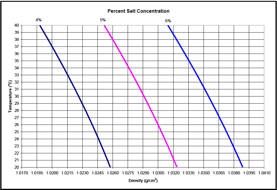
Figure description:
Percent Salt Concentration
Percent Salt Concentration
Legend
- 4% Salt Concentration — color: dark blue; symbol: Solid line
- 5% Salt Concentration — color: pink; symbol: Solid line
- 6% Salt Concentration — color: blue; symbol: Solid line
| Temperature (°C) | 4% Salt Density (g/cm³) | 5% Salt Density (g/cm³) | 6% Salt Density (g/cm³) |
|---|---|---|---|
| 40 | 1.0188 | 1.0264 | 1.0333 |
| 39 | 1.0192 | 1.0267 | 1.0336 |
| 38 | 1.0195 | 1.0270 | 1.0339 |
| 37 | 1.0199 | 1.0273 | 1.0342 |
| 36 | 1.0202 | 1.0276 | 1.0345 |
| 35 | 1.0206 | 1.0280 | 1.0348 |
| 34 | 1.0209 | 1.0283 | 1.0351 |
| 33 | 1.0213 | 1.0286 | 1.0354 |
| 32 | 1.0216 | 1.0289 | 1.0357 |
| 31 | 1.0220 | 1.0293 | 1.0360 |
| 30 | 1.0223 | 1.0296 | 1.0363 |
| 29 | 1.0227 | 1.0299 | 1.0366 |
| 28 | 1.0230 | 1.0302 | 1.0369 |
| 27 | 1.0234 | 1.0305 | 1.0372 |
| 26 | 1.0237 | 1.0308 | 1.0375 |
| 25 | 1.0241 | 1.0311 | 1.0378 |
| 24 | 1.0244 | 1.0315 | 1.0381 |
| 23 | 1.0248 | 1.0318 | 1.0384 |
| 22 | 1.0251 | 1.0321 | 1.0387 |
| 21 | 1.0255 | 1.0324 | 1.0390 |
| 20 | 1.0258 | 1.0327 | 1.0393 |
Notes: The chart shows the linear relationship between the density of saltwater and its temperature for three different salt concentrations (4%, 5%, and 6%. Density decreases linearly as temperature increases. The labels for each concentration are placed at the top of their respective lines.)
Figure 509.7-3. Variations of density of salt (NaCl) solution with temperature.
| Temperature °C (°F) | Density g/cm³ | ||
|---|---|---|---|
| 4-percent Salt Concentration | 5-percent Salt Concentration | 6-percent Salt Concentration | |
| 20 (68) | 1.025758 | 1.032360 | 1.038867 |
| 21 (69.8) | 1.025480 | 1.032067 | 1.038560 |
| 22 (71.6) | 1.025193 | 1.031766 | 1.038245 |
| 23 (73.4) | 1.024899 | 1.031458 | 1.037924 |
| 24 (75.2) | 1.024596 | 1.031142 | 1.037596 |
| 25 (77) | 1.024286 | 1.030819 | 1.037261 |
| 26 (78.8) | 1.023969 | 1.030489 | 1.036919 |
| 27 (80.6) | 1.023643 | 1.030152 | 1.036570 |
| 28 (82.4) | 1.023311 | 1.029808 | 1.036215 |
| 29 (84.2) | 1.022971 | 1.029457 | 1.035853 |
| 30 (86) | 1.022624 | 1.029099 | 1.035485 |
| 31 (87.8) | 1.022270 | 1.028735 | 1.035110 |
| 32 (89.6) | 1.021910 | 1.028364 | 1.034729 |
| 33 (91.4) | 1.021542 | 1.027986 | 1.034343 |
| 34 (93.2) | 1.021168 | 1.027602 | 1.033950 |
| 35 (95) | 1.020787 | 1.027212 | 1.033551 |
| 36 (96.8) | 1.020399 | 1.026816 | 1.033146 |
| 37 (98.6) | 1.020006 | 1.026413 | 1.032735 |
| 38 (100.4) | 1.019605 | 1.026005 | 1.032319 |
| 39 (102.2) | 1.019199 | 1.025590 | 1.031897 |
| 40 (104) | 1.018786 | 1.025170 | 1.031469 |
4.5.1.2 Pretest Standard Ambient Checkout
All items require a pretest checkout at room ambient conditions to provide baseline data. Conduct the checkout as follows:
Step 1. Prepare the test item in its required configuration in accordance with Part One, paragraph 5.8.1.
- Step 2. Record the room ambient temperature and humidity to determine if within standard ambient.
Step 3. Conduct a complete visual examination of the test item with attention to:
- (1) High-stress areas.
- (2) Areas where dissimilar metals are in contact.
- (3) Electrical and electronic components - especially those having closely spaced, unpainted or exposed circuitry.
- (4) Metallic surfaces.
- (5) Enclosed volumes where condensation has occurred or may occur.
- (6) Components or surfaces provided with coatings or surface treatments for corrosion protection.
- (7) Cathodic protection systems; mechanical systems subject to malfunction if clogged or coated with salt deposits.
- (8) Electrical and thermal insulators.
NOTE: Consider partial or complete disassembly of the test item if a complete visual examination is required. Be careful not to damage any protective coatings, etc. during disassembly or reassembly.
Step 4. Document the results. (Use photographs, if necessary.)
- Step 5. Conduct an operational checkout in accordance with the test plan, and record the results for compliance with Part One, paragraph 5.9.
- Step 6. If the test item meets the requirements of the test plan or other applicable documents, proceed to Step 1 of the test procedure below. If not, resolve any problems and restart the pretest standard ambient checkout at the most reasonable step above.
4.5.2 Procedure
- Step 1. With the test item in the chamber, adjust the test chamber temperature to 35 °C (95 °F), and condition the test item for at least two hours before introducing the salt fog.
- Step 2. Continuously atomize a salt solution of a composition as given in paragraph 4.5.1.1b into the test chamber for a period of 24 hours or as specified in the test plan (see paragraph 2.2.3). During the entire exposure period, measure the salt fog fallout rate and pH of the fallout solution at least at 24- hour intervals3/. Ensure the fallout is between 1 and 3 ml/80 cm2/hr with a pH between 6.5 and 7.2.
- Step 3. Dry the test item at standard ambient temperatures and a relative humidity of less than 50 percent for 24 hours, or as otherwise specified (see paragraph 2.2.3). Minimize handling the test item or adjusting any mechanical features during the drying period.
- Step 4. If the 48/48-hrs option has been chosen, proceed to Step 5. Otherwise, at the end of the drying period, repeat steps 1 to 3 at least once.
- Step 5. After completing the physical and any electrical checkouts, document the results with photographs. See paragraph 5 for analysis of results. If necessary to aid in the follow-on corrosion examination, use a gentle wash in running water that is at standard ambient conditions, conduct the corrosion examination, and document the results with photographs.
Step 6. Visually inspect the test item in accordance with the guidelines given in paragraph 4.5.1.2.