519.8-2 DEVELOPMENT
519.8-2 BASIC CONSIDERATIONS FOR GENERATION OF A DETERMINISTIC GUNFIRE SHOCK TIME HISTORY FROM A SRS ESTIMATE
519.8-2 DEVELOPMENT
519.8-2 RECOMMENDED PROCEDURES
2.1 Selecting the Gunfire Shock Method
After examining requirements documents and applying the tailoring process in Part One of this Standard to determine where exposure to a gunfire shock environment is foreseen in the life cycle of the materiel, use the following to confirm the need for this Method and to place it in sequence with other methods.
519.8-2.1 Basic Considerations for Environmental Determination
In-service measured data collection is performed with properly instrumented materiel where the measurements are made at pre-selected points either as input to the materiel or as response from the materiel. If the measurement points are on the materiel then the measurement points exhibit minimum local resonances, yet the measurement locations will allow the detection of significant overall materiel resonances. The measurement locations may be determined prior to an in-service measurement effort by examination of random vibration data on the materiel using various accelerometer mounting locations and fixture configurations (the in-service measurement or reference point should be the same as the laboratory control point). The in-service measured data should be DC coupled (preferably), or at least high pass filtered below the most significant frequency that can be replicated in the laboratory. For an electrohydraulic exciter, information close to DC in the measurement time trace can be replicated, however, for an electrodynamic exciter measurement data high pass filtered above 5 Hz will be acceptable. The measurement time trace should be sampled at ten times the highest frequency of interest, with appropriate anti-alias filtering applied (this applies for either direct digital recording or digitizing an analog voltage signal from a recording device). The measured time history trace should be examined for any evidence of signal clipping, or any accelerometer performance anomalies, e.g., zero shifting. If there is indication of accelerometer measurement anomalies, the potentially corrupted acceleration time trace should be carefully examined according to the procedures used in validation of mechanical shock data (see paragraph 6.1 reference b). For example time trace integration to examine velocity and displacement characteristics and the computation of sample probability density function (PDF) estimates may provide information on invalid time traces. If there is no indication of accelerometer anomalies, digitally band pass filter the in-service measured time trace consistent with the exciter replication bandwidth, and place it in a digital file designated the reference time trace for TWR testing under Method 525.2 (SESA). This procedure for preparing the reference time trace for TWR is usually performed with a personal computer (PC) with signal processing capability. A test of gunfire shock replication on an electrodynamic exciter using Procedure I under guidelines in Method 525.2 is provided for illustration purposes below. Application of test tolerance assessment for Procedure I is illustrated.
519.8-2.1 Introduction
It is assumed that an SRS over a given natural frequency bandwidth is available for description of the gunfire shock event assumed to be a product of a form of replicated shock and TWR is the prescribed method of test. It is assumed that the natural frequency bandwidth is compatible with the laboratory test apparatus i.e., electrodynamic or electro hydraulic exciter. Procedure II will be illustrated for a generic SRS gunfire shock specification.
519.8-2.1 Introduction
This Annex is essentially a reorganized reproduction of the information contained in reference g. of paragraph 6.1, with some additional guidance. Mention of the pulse method in paragraph 6.2, reference f, is included, and provides insight into the use of the pulse method in conjunction with a predictive rationale. Procedure III differs from the other two procedures in that it is a result of a prediction procedure developed on the basis of an analysis of a comparatively small set of measured gunfire materiel response data. The predicted spectrum, therefore, provides estimates of materiel vibration response that may be substantially different from in-service measured vibration response of a particular materiel. For a particular materiel and gun/materiel configuration, materiel response to gunfire is generally not amenable to accurate prediction. The prediction methodology provided below is generally subject to a large degree of uncertainty with respect to test level. This uncertainty is very apparent in gunfire configurations where the gun is less than a meter (3.3 ft) from the materiel.
MIL-STD-810H METHOD
519.8-2.1 Recommended Procedure
For aircraft vibration for materiel mounted in the aircraft with no available measured data, use this procedure with the prediction methodology implemented with the TDWP or RMHP.
2.1.1 Effects of a Gunfire Shock Environment
Exposure to a gunfire shock environment has the potential for producing adverse effects on the structural and functional integrity of all materiel including in-service operational capability. The probability of adverse effects increases with the blast energy of the gun, proximity of the materiel to the gun, and the duration of the gunfire shock environment. The gunfire firing rate and the duration of gunfire shock environment exposure that correspond with natural frequencies of the mounted materiel (along with its sub-harmonics and super-harmonics) will magnify the adverse effects on the materiel’s overall integrity.
MIL-STD-810H METHOD 519.8
2.1.2 Sequence among Other Methods
- a. General. Use the anticipated life cycle sequence of events as a general sequence guide (see Part One, paragraph 5.5).
- b. Unique to this Method. Sequencing among other methods will depend upon the type of testing, i.e., design developmental, qualification, endurance, etc., and the general availability of test items. Normally, schedule gunfire shock tests early in the test sequence, but after significant levels of vibration, thermal, and mechanical shock tests. For thermal testing include any potential transient thermal effects from gunfire on the materiel. Note that in the Life Cycle Environmental Profile (LCEP) gunfire shock is represented as a series of events according to a “gunfire schedule,” such that the total exposure time is usually substantially less than exposure to random vibration environment(s).
- (1) If the gunfire shock environment is deemed particularly severe and the chances of materiel survival without major structural and/or functional failure are small, perform the gunfire shock test first in the test sequence. This provides the opportunity to redesign the materiel to meet the gunfire shock requirement before testing to the potentially more benign vibration and/or mechanical shock environments.
- (2) If the gunfire environment is considered severe, but the probability of the materiel survival without structural and/or functional failure is good, perform the gunfire shock test after vibration, thermal, and mechanical shock tests, allowing the stressing of the test item to long duration environments prior to gunfire shock testing. This order of testing is intended to uncover combined temperature and vibration/shock environmental failures. (There are often advantages to applying gunfire shock tests before climatic tests, provided the sequence represents realistic service conditions. Climate-sensitive defects often show up more readily after the application of severe gunfire shock environments. However, internal or external thermal stresses may permanently weaken materiel resistance to vibration, mechanical shock, and gunfire shock that may go undetected if gunfire shock tests are applied before climatic tests.)
- (3) In cases in which the gunfire shock test levels are deemed less severe than the vibration test levels, the gunfire shock tests may be deleted from the testing sequence. However, credible modeling and analysis procedures must be employed that lead to concluding that gunfire shock levels are actually less severe than vibration test levels. This may require the predicted or measured gunfire shock environment be of the form of a short duration transient vibration with some periodic structure, as opposed to a replicated shock, and that the short duration transient vibration be analyzed in accordance with either stationary vibration procedures or procedures related to processing the product model for non-stationary environments.
- (4) It is never acceptable to automatically conclude that gunfire shock test levels are less severe than mechanical shock test levels. Gunfire shock is of a repeated shock nature at the firing rate of the gun as opposed to a single mechanical shock. Methods for comparing the severity of shock, e.g., SRS, cannot be credibly used to assess the severity of test levels between gunfire shock and simple mechanical shock.
- (5) The gunfire shock environment may affect materiel performance when materiel is tested simultaneously to other environmental conditions such as vibration, temperature, humidity, pressure, etc. If materiel is known to be sensitive to a combination of environments, test to those environments simultaneously (possibly superimposing the gunfire shock environment on the random vibration environment). If it is impractical to test to a combination of environments simultaneously, and where it is necessary to evaluate the effects of the gunfire shock environment together with other environments, expose a single test item to all relevant environmental conditions in turn. In general, gunfire shock may occur at any time during the specified operational conditions, so sequence it as close as practical to the sequencing defined in the life cycle environmental profile. If in doubt, as recommended in this paragraph, conduct gunfire shock testing immediately after completing any vibration and mechanical shock testing.
MIL-STD-810H METHOD 519.8
2.2 Selecting a Procedure
This Method includes three procedures. Gunfire shock testing to significant environmental levels is generally limited by the guidelines provided in Method 525.2, Time Waveform Replication. In particular, all the guidelines in Method 525.2 relative to time trace scaling and simulation must be strictly adhered to. If the materiel, because of its distance from the gun, may be exposed to a gunfire shock environment even lower than measured vibration levels from other sources, separate testing to a gunfire shock environment may not be necessary to ensure materiel integrity. It is absolutely essential field measured time trace information representing particular materiel response to the gunfire shock environment be examined before guidelines found in Method 525.2 are applied. There are few, if any, reliable analytical techniques for accurately predicting low levels of materiel response to gunfire shock environment, except for obvious physical configuration assessment, e.g., the gun is on the opposite side of the aircraft fuselage from the materiel. Consider low gunfire shock environments as transient vibration environments rather than long duration stationary random vibration environments because of LCEP gunfire scheduling. Perform testing to transient vibration environments in accordance with Method 525.2. To execute laboratory testing this Method provides for the following three procedures:
Procedure I: MEASURED MATERIEL INPUT/RESPONSE TIME HISTORY UNDER TWR
Procedure II: SRS GENERATED SHOCK TIME HISTORY PULSE SEQUENCE UNDER TWR
Procedure III: STOCHASTICALLY GENERATED MATERIEL INPUT FROM PRELIMINARY DESIGN SPECTRUM UNDER TWR
519.8-2.2 Test Configuration
A specially instrumented unidentified test item is installed in a laboratory vibration fixture and mounted on an electrodynamic exciter. The test item employed during the laboratory testing is of the same general materiel configuration that was used to collect the gunfire shock materiel response information during an in-service test
MIL-STD-810H
METHOD
519.8-2.2 Single Gunfire Shock Event with SRS Specification
Figure 519.8B-1 illustrates a generic maximax SRS representing a “gunfire event” with “event” implying “replicated shock” at the gunfire rate. The SRS is termed the “Target SRS” implying that this SRS must be satisfied in the testing procedure within tolerances provided in Method 516.8. The gunfire rate is specified as 50 Hz providing a fundamental pulse repetition at 20 millisecond time intervals. The natural frequency bandwidth is from 10 to 2000 Hz. All SRS computations in the example were computed with a one-twelfth octave resolution and Q=10. For this example, assume the gunfire schedule calls for firing 10 bursts of 1 second duration i.e., 50 pulses and a gunfire schedule separation of 2 seconds between bursts. For this specification the natural frequency bandwidth is compatible with the bandwidth of the electrodynamic exciter for Method 525.2 TWR testing.
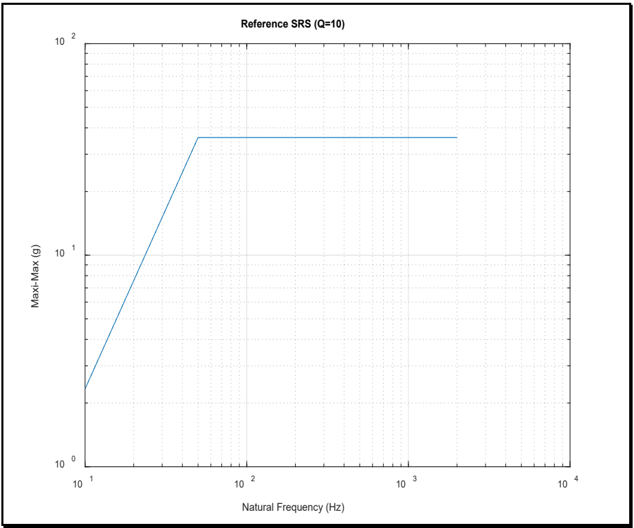
Figure description:
Reference SRS (Q=10
Reference SRS (Q=10
| Natural Frequency (Hz) | Maxi-Max (g) |
|---|---|
| 10 | 2.5 |
| 50 | 40 |
| 2000 | 40 |
Notes: The chart displays a Shock Response Spectrum (SRS on a log-log scale. The response levels off at 40g between 50 Hz and 2000 Hz.)
MIL-STD-810H METHOD
519.8-2.2 Predicting Gunfire Vibration Spectra
Gunfire vibration prediction spectra consist of a broadband spectrum representative of an ASD estimate from stationary random vibration, along with four harmonically related sine waves. Figure 519.8C-1 provides a generalized vibration spectrum for gunfire-induced vibration that defines the predicted response of materiel to a gunfire environment. It is characterized by four single frequency harmonically related (sine) vibration peaks superimposed on a broadband random vibration spectrum. The vibration peaks are at frequencies that correspond to the nominal gunfire rate and the first three harmonics of the gun firing rate. The specific values for each of the parameters shown on Figure 519.8C-1 can be determined from Table 519.8C-I, Table 519.8C-II, Table 519.8C-III, and Figures 519.8C-2 through -8. The suggested generalized parametric equation for the three levels of broadband random vibration, Tj, defining the spectrum on Figure 519.8C-1, is given in dB for g²/Hz (reference to 1 g²/Hz) as:
10log10 (Tj) = 10log10 (N F₁ E) + H+M+W+J+B;- 53 dB j=1, 2, 3 Equation (C-1)
where the parameters are defined in Table 519.8C-I. The suggested generalized parametric equation for the four levels of single frequency (sine) vibration defining the spectrum on Figure 519.8C-1 is given in dB for g²/Hz (reference to 1 g²/Hz) as
10log10 (Pi) 10log10 (T3) + Ki +17 dB i=1, 2, 3, 4 Equation (C-2)
where the parameters are defined in Table 519.8C-I.
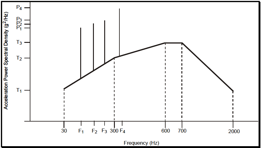
Figure description:
Acceleration Power Spectral Density Specification
Acceleration Power Spectral Density (g²/Hz vs Frequency (Hz
Annotations
- Low frequency limit (vertical_line - position: x = 30)
- Breakpoint frequency 1 (vertical_line - position: x = 300)
- Plateau start frequency (vertical_line - position: x = 600)
- Plateau end frequency (vertical_line - position: x = 700)
- High frequency limit (vertical_line - position: x = 2000)
| Frequency (Hz) | Background PSD Profile (g²/Hz) | Spectral Peaks (g²/Hz) |
|---|---|---|
| 30 | T1 | null |
| F1 | null | P1 |
| F2 | null | P2 |
| F3 | null | P3 |
| 300 | T2 | null |
| F4 | null | P4 |
| 600 | T3 | null |
| 700 | T3 | null |
| 2000 | T1 | null |
Notes: The graph depicts a typical vibration test profile consisting of a continuous broadband background PSD envelope with four discrete narrowband spectral peaks superimposed. The background profile is defined by breakpoints at (30, T1, (300, T2, (600, T3, (700, T3, and ends at (2000, T1. The peaks are located at frequencies F1, F2, F3, and F4, with levels P1, P2, P3, and P4 respectively.)))))
Figure 519.8C-1. Generalized gunfire induced vibration spectrum shape.
MIL-STD-810H METHOD
519.8-2.2 Uncertainty Factors
This procedure contains two sources of uncertainty. First, there is uncertainty in application of the SOR prediction methodology and determining a SOR spectrum. Second, there is uncertainty in transferring information in the SOR prediction methodology to a form of laboratory test that might be appropriate for materiel design considerations.
2.2.1 Procedure Selection Considerations
Based on test or preliminary design requirements, determine which test procedure, combination of procedures, or sequence of procedures is applicable. In many cases, one or more of the procedures will apply. For example, Procedure I may be the basis when measured gunfire response data are available. Procedure II will be required if measurement information is processed with the SRS as distinct shocks or as a SRS of the overall shock and measurement time history information is no longer available. If measurement time history information is available then Procedure I is recommended. For procedures in which there is a general lack of field measured data, Procedure III may be used to predict the gunfire repetitive shock environment and a gunfire shock time history produced under two ad hoc processes described in Procedure III. Consider all gunfire shock environments anticipated for the materiel during its life cycle, in its operational modes. When selecting procedures, consider:
- a. Measured Materiel Response Available. If field measured time trace materiel input/response data are available, it is recommended that this information be used in development of a test specification. Generally, the test specification will require that laboratory testing be in accordance with the guidelines provided in Method 525.2. Generally, Method 525.2 is the only method suitable for measured time traces that have the form of a repetitive shock at the firing rate of the gun over a given duration in the gunfire schedule.
- b. Measured Materiel Response Unavailable. If field measured time trace data for materiel are unavailable, the following considerations are important.
- (1) First, there are no known reliable means of predicting gunfire shock materiel input/response based on gun and materiel configuration descriptions. Previous versions of MIL-STD-810 beginning with MIL-STD-810C provided a means of developing a predicted Sine-on-Random (SOR) vibration test spectrum based upon several gun/materiel configuration parameters. Information for predicting the SOR spectrum is thought to be too limited to be reliable.
- (2) Second, it is recognized that in the early design and development of materiel, some guidance on levels of input excitation to the materiel are needed, and generally vibration or mechanical shock levels are not appropriate when significant materiel response to gunfire shock is anticipated.
- (3) Third, the methodology for analysis of the measured response to gunfire shock was a major weakness in development of the predicted SOR spectrum. A SOR model is inadequate for modeling a repetitive pulse environment. The primary inadequacy in the modeling is the accurate representation of the repetitive pulse rise time. Four harmonically-related sine components added to stationary random vibration provide for a consistent rise time well below that for a repetitive shock environment, and appear to be too long for significant gunfire shock input excitation or even measured materiel response. Recent gunfire shock measurement data reveals substantial rise time
responses and the sensitivity of the form of a single gunfire shock time trace to gun/materiel configuration.
- (4) Finally, there is a methodology that allows use of the predicted SOR spectrum information in the form of a repetitive pulse. This methodology requires preliminary design procedures be in accordance with that for repetitive shock at predicted SOR spectrum levels. This philosophy has been adopted for the stochastic prediction incorporated in Procedure III.
As a rationale related note on Procedure III, even though the set of measured data available in the mid-1970s was small for the extended prediction philosophy that was developed, there was hesitation in discarding the information in previous versions of MIL-STD-810. Accordingly (in light of the unavailability of other information to confirm the prediction methodology), use of the predicted information (SOR spectrum) in the form of a repetitive shock for preliminary design purposes, is acceptable. Part of the reasoning behind this is that the predicted information tends to scale correctly from a strictly logical point of view. Annex C provides guidelines for specifying preliminary repetitive shock based design environments from the prediction algorithm provided in this Annex. The materiel designer must be prepared to design to a form of repetitive shock input to the materiel at the gunfire rate.
It is assumed in applying any of the three procedures, the dynamics of the materiel are well known; in particular, the resonances of the materiel and the relationship of these resonances to the gun firing rate and its harmonics. In addition, it is assumed that any vibration/shock isolation characteristics between gun and materiel configuration are understood. Improper test procedure selection and execution may result in either a non-conservative materiel under-test, or a substantial materiel over-test. These procedures can be expected to cover a substantial range of testing related to materiel exposed to gunfire shock environment. In summary:
For severe materiel response to gunfire shock environment with measured time trace data, use Procedure I or Procedure II in conjunction with Method 525.2.
For benign materiel response to gunfire determined from measured time trace data, examine the need for testing to gunfire shock when other vibration or mechanical environments are prescribed. If the need persists, consider testing to a transient vibration environment under the guidelines in Method 525.2.
For no measured materiel response time history data, use the methodology outlined in Procedure III to predict preliminary gunfire repetitive shock levels and in an ad hoc manner generate repetitive shock time histories.
- c. The operational purpose of the materiel. From requirement documents, determine the operations or functions to be performed by the materiel before, during, and after exposure to the gunfire shock environment.
- d. The natural exposure circumstances. Materiel response to a gunfire shock environment is heavily dependent upon the caliber of the gun and the physical configuration of the gun relative to the materiel.
- e. Data required. The test data required to document the test environment and to verify the performance of the materiel before, during, and after the test.
- f. Procedure sequence. Refer to paragraph 2.1.2.
519.8-2.2.1 SOR Prediction Methodology Uncertainty
There is substantial uncertainty in general levels because of the sensitivity of the gunfire environment to gun parameters and geometrical configuration. It may be appropriate to increase levels or durations in order to add a degree of conservativeness to the testing. Change in levels, durations, or both for the sake of increasing test conservativeness must be backed up with rationale and supporting assessment documentation. Since extreme spectra prediction levels do not necessarily provide test inputs that correlate with measured data (for the same geometrical configuration), the uncertainty in damage potential is increased substantially as the predicted spectra increase in level; i.e., testing with this procedure may be quite un-conservative.
MIL-STD-810H METHOD
2.2.2 Difference among Procedures
- a. Procedure I. MEASURED MATERIEL INPUT/RESPONSE TIME HISTORY UNDER TWR. Measured in-service gunfire shock environment for materiel is replicated under laboratory exciter waveform control (Method 525.2 TWR) to achieve a near exact reproduction of the measured in-service gunfire shock environment. Test philosophy includes selection of the time trace or traces to be replicated according to the scope of the test. Use the guidelines provided in Annex A and in Method 525.2.
- b. Procedure II. SRS GENERATED SHOCK TIME HISTORY PULSE SEQUENCE UNDER TWR. This procedure is based on former processing measured gunfire shock in terms of the SRS applied either to individual gunfire pulses or the SRS applied to the overall gunfire pulse sequence (it is assumed that time history
MIL-STD-810H
METHOD 519.8
information is no longer available for application of Procedure I). It is critical that percent of critical damping considered in computation of the SRS is known. The gunfire rate of interest must also be defined. The gunfire rate will define a parameter . Ideally, the "concentration of energy", will also be provided (see Method 516.8 for a discussion of and ). If the SRS is applied to individual gunfire pulses some form of "enveloping" the individual SRS estimates may be employed as described in Method 516.8 Annex B. In either case a single SRS estimate is obtained that can be used to generate a single shock pulse time history based upon waveform synthesis or other technology. This single shock pulse time history then can be concatenated into a shock pulse series and run under TWR. Stochastic variations with departures from single pulse generation are permitted.
- c. Procedure III. STOCHASTICALLY GENERATED MATERIEL INPUT FROM PRELIMINARY DESIGN SPECTRUM UNDER TWR. This procedure is ad hoc, lacking necessary field measured time trace information, and a last resort to providing guidelines for design of materiel to resist a gunfire shock environment. Only time trace forms for design are given, and it is not suggested that testing be performed to these forms for materiel qualification purposes. The shortcomings of previous MIL-STD-810 versions and use of prediction methods are outlined in paragraph 2.2.1. The inability to develop a database useful for prediction is unfortunate, and the reluctance to discard what little prediction information that is available has resulted in this procedure. The idea behind this procedure is that the true nature of either air-borne or structure-borne gunfire shock is impulsive in nature at the gunfire rate. Any initial design of materiel must be on the basis of a repetitive shock pulse as opposed to stationary random vibration with added sine components. Annex C provides an outline of limited procedures that stochastically generate pulse time traces for preliminary design when no measured gunfire shock information is available.
519.8-2.2.2 Stochastic TWR Generation Uncertainty
There is uncertainty in the stochastic implementation of either TDWP or RMHP. Materiel response to gunfire environment either via air borne or structure borne stimulation is complex in part because of the transmission path and the medium through which the “gunfire pulse” must travel to impact the materiel. Neither TDWP nor RMHP can account for the physical phenomenon or its effects on the materiel. TDWP can control certain time domain properties by variation in the exponential pulse and is transparent in this manner. TDWP is generally for high level gunfire response where there is a substantial regularity in the pulse structure even though this pulse structure i.e., the exponential window could easily be varied deterministically or stochastically. RMHP is more uncontrolled but may be able to satisfy some of the higher order correlation information contained in gunfire records, in particular any periodically correlated aspects of gunfire, even though this has not been studied extensively. The random generated pulses can be generated, characterized, and stored for a more refined stochastic simulation. Just by repeated stochastic generation portions of time history record can be identified with targeted kurtosis values. Either technique can be said to be totally uncertain relative to what measurements might be obtained based upon the SOR prediction configuration.
Downloaded from https://www.everyspec.com
MIL-STD-810H METHOD 519.8 ANNEX C
(This page is intentionally blank.)
MIL-STD-810H
METHOD 520.5
METHOD
2.3 Determine Test Levels and Conditions
Having selected this Method and relevant procedure(s) (based on the materiel’s requirements documents and the tailoring process), complete the tailoring process by identifying appropriate parameter levels, applicable test conditions, and test techniques for the selected procedures. Base these selections on the requirements documents and the LCEP, and information provided with this procedure. Consider the following when selecting test levels.
519.8-2.3 Creating a Digital File of the Measured Gunfire Shock Input to the Materiel
A first step is to formulate a test strategy and carefully examine the available measured time trace information designed to satisfy the test strategy. Usually, selection of a test strategy is based upon the materiel LCEP. The test strategy may consist of selection of the maximum measured environment for replication according to some criteria, e.g., peak acceleration, maximum energy, etc. The test strategy may also consist of selection of several levels of measured environment to be run sequentially in proportion to the level of the particular environment expected in the LCEP. For the illustration, the maximum measured level that provided gunfire shock transition from 2000 rounds/minute to 4000 rounds/minute was selected based upon a visual inspection of the in-service test measured data. Figure 519.8A-1 provides an unprocessed time trace from a measured in-service digital recording. The time trace is from the same gun/materiel configuration, for the same event and in one of three mutually orthogonal axes termed the horizontal axis. The in-service measurement was made on a digital recorder with simultaneous channel record capability in the multiple axes with a sample rate of 102400 sps, and an anti-alias filter set at 8000 Hz. The time trace measurement bandwidth exceeds the bandwidth of the exciter system to be used for replication.
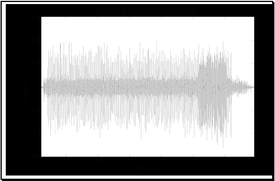
Figure description:
In Service Measured Horizontal Acceleration
In Service Measured Horizontal Acceleration
| Time (sec) | High Amplitude Signal Peak (g) | Low Amplitude Signal Peak (g) |
|---|---|---|
| 8.2 | 315 | 45 |
| 8.5 | -390 | -50 |
| 8.8 | 380 | 40 |
| 9.1 | -360 | -55 |
| 9.4 | 395 | 50 |
| 9.7 | -340 | -45 |
| 10.0 | 365 | 55 |
| 10.3 | -405 | -60 |
| 10.6 | 375 | 45 |
| 10.9 | -385 | -50 |
| 11.2 | 390 | 65 |
| 11.5 | -370 | -40 |
| 11.8 | 385 | 55 |
| 12.1 | -400 | -50 |
| 12.4 | 360 | 45 |
| 12.7 | -380 | -60 |
| 13.0 | 345 | 50 |
| 13.3 | 470 | 75 |
| 13.6 | -505 | -80 |
| 13.9 | 420 | 70 |
| 14.2 | -295 | -45 |
| 14.5 | 105 | 25 |
| 14.8 | -25 | -10 |
| 15.0 | 0 | 0 |
Notes: The chart displays two overlaid high-frequency signals. One (light gray has a much higher amplitude, generally ranging between -400 and +400 g, with a noticeable increase in intensity and amplitude between 13 and 14 seconds. The second signal (darker gray/black is much lower in amplitude, generally staying within the -75 to +75 g range.))
Figure 519.8A-1. In-service measured gunfire shock: unprocessed time trace (2000 round/min and 4000 round/min).
The second step in the measured environment replication process is to determine a laboratory test bandwidth, and to provide one or more specific digitized measured in-service time traces. The measured in-service time trace must be sampled (or interpolated from an adequate measurement bandwidth) at a minimum of ten times the highest frequency of interest for testing in order to best capture peak time trace information. The laboratory test bandwidth for the electrodynamic exciter is 10 Hz to 2000 Hz.
MIL-STD-810H
METHOD 519.8 ANNEX A
519.8-2.3 Multiple Gunfire Shock Events with SRS Considerations
When multiple gunfire shock events for SRS estimates are provided then laboratory testing may proceed as in paragraph 2.2 for a single gunfire shock event applied by each of the multiple gunfire shock events.
One acceptable means of providing a form of stochastic implementation of the SRS procedure is to create deterministic SRS sine-beat based pulse time histories based upon SRS estimates for independent gunfire event time histories. That is, for each gunfire event a series of “sine-beat pulses” is generated and concatenated into one overall pulse time history. The statistical variation in the individual gunfire events can be represented by this procedure. This procedure can also be used to produce a very large number of unique and statistically independent overall gunfire time history events by Monte-Carlo sampling of the SRS sine beat generation.
519.8-2.3 Duration of Test
Use a duration for the gunfire vibration test in each of the three axes that is equivalent to the expected total time the materiel will experience the environment in in-service use. This duration may be conservatively estimated by multiplying the expected number of aircraft sorties in which gun firing will occur by the maximum amount of time that gun firing can occur in each sortie. The number of sorties in which gunfire will occur will be associated with planned aircraft training and combat use rates, but will generally be in the vicinity of 200 to 300 sorties. The maximum time of gunfire per sortie can be determined from Table 519.8C-II by dividing total rounds per aircraft by the firing rate. When a gun has more than one firing rate, perform the test using both firing rates, with test time at each firing rate based on the expected proportion of time at each firing rate for in-service use. The guns carried by an aircraft are generally fired in short bursts that last a few seconds. Testing to a gunfire environment should reflect a form of in-service use in compliance with the test plan. For example, vibration could be applied for two seconds followed by an eight-second rest period during which no vibration is applied. This two-second-on/eight-second-off cycle is repeated until the total vibration time equals that determined for the aircraft type and its in-service use. This cycling will prevent the occurrence of unrealistic failure modes due to vibration isolator overheating or buildup of materiel response in continuous vibration. Intermittent vibration can be achieved by several means including (1) the interruption of the exciter input signal, and (2) a waveform replication strategy for transient vibration discussed in Annex A.
2.3.1 General Considerations
Establish the test severities using available measured gunfire shock time trace data from a similar gun/materiel configuration, or measured gunfire shock time trace data acquired directly from an environmental measurement program. When these data are not available, some limited information on test severities and guidance may be found in Annex C. The procedure selected may not provide an adequate test for the complete environment; thus, a supporting assessment may be necessary to compliment the test results.
2.3.2 Test Conditions
In all cases care must be taken to replicate the measured environmental materiel response data that may require establishing the correct interface impedances. When measured data are not available, the input to the materiel or the materiel response must be in accordance with that defined in Procedure III for prediction. Many laboratory shock tests are conducted under standard ambient test conditions as discussed in Part One, paragraph 5. However, when the life cycle events being simulated occur in environmental conditions significantly different than standard conditions, consider applying those environmental factors during testing.
2.3.3 Test Axes and Number of Gunfire Shock Events
The test axes should be in accordance with the physical configuration for the in-service environment. Material response to gunfire pressure pulses will generally involve testing in axes normal to the primary pressure pulse emanation axis. Materiel response to structure-borne vibration will generally involve testing in all axes. The number of gunfire events should be in accordance with the Life-Cycle Environmental Profile document. In general, it is permissible to test using Single-Exciter/Single-Axis (SESA), Method 525.2 (TWR) methodology in all axes of concern. However, for particularly sensitive materiel whereby the operational integrity of the materiel must be ensured with a high degree of confidence, testing may be performed under the guidelines of Multiple-Exciter/Multiple-Axis (MEMA) methodology given under Method 527.2. Under highly specialized conditions, when materiel degradation under gunfire shock is very likely, it may be necessary to consider multiple gunfire events according to LCEP gunfire schedules modeled probabilistically as Poisson in nature, with either a stationary or non-stationary gunfire event rate.
Generally, because of the unique character of gunfire shock, it is not acceptable to “scale” individual measured gunfire time traces in the time domain in order to achieve test conservativeness and reduce test repetitions. However, for frequency domain ensembles of a set of gunfire time histories e.g., a SRS ensemble, it is possible to summarize the ensemble in the frequency domain and use the summary to create an acceptable laboratory test time history for TWR. Generally, the created laboratory test time history will be distinct from measurements forming the ensemble but representative of what might possibly be a future measurement.
2.4 Test Item Configuration. (See Part One, Paragraph 5.8.)
Configure the test item for gunfire shock testing as would be anticipated during in-service use, including particular attention to the details of the in-service mounting of the materiel to the platform. Gunfire response is sensitive to the details of the materiel/platform configuration and input impedances.
519.8-2.4 Replicating the Measured Gunfire Shock Materiel Input in Laboratory Test
Once the test strategy has been formulated and the measured time trace obtained digitally, as a third step, the band limited time trace is input to the vendor supplied TWR hardware/software that drives an electrodynamic exciter. Guidelines for performing the test are provided in Method 525.2 and will not be repeated here. As outlined in paragraph 4.2, if such testing is critical for materiel qualification, a dynamic simulant of the materiel may be used to compensate the exciter system for the input time trace. Once this compensation is complete, the dynamic simulant is replaced by the test item. Figure 519.8A-2 provides the reference, control, and difference time traces as a result of the testing to the band-limited reference time trace. Note that visual comparison of the reference and control time traces reveals the same character and the same general magnitude. The difference time trace computed by subtracting the reference time trace from the control time trace (see Method 525.2) reveal substantial peak and valley differences indicative of out-of-band energy within the control time trace as a result of impedance and boundary condition mismatch. For this illustrative test series, (1) a dynamic simulant was not used for reference time trace compensation, and (2) an optimum control strategy for additional compensation was not employed. Despite impedance and boundary condition mismatches, the general test error could have been reduced by employing a better compensation strategy.
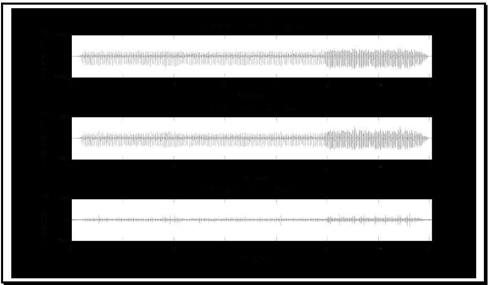
Figure description:
Reference : TWR Horizontal
| Time (sec) | Acceleration (g) |
|---|---|
| 0.0 | 0 |
| 0.2 | 105 |
| 0.5 | 45 |
| 1.0 | 60 |
| 1.5 | 55 |
| 2.0 | 65 |
| 2.5 | 50 |
| 3.0 | 40 |
| 3.5 | 42 |
| 4.0 | 45 |
| 4.5 | 40 |
| 5.0 | 60 |
| 5.2 | 90 |
| 5.5 | 110 |
| 5.8 | 125 |
| 6.0 | 115 |
| 6.2 | 130 |
| 6.5 | 100 |
| 6.8 | 60 |
| 7.0 | 0 |
Control : TWR Horizontal
| Time (sec) | Acceleration (g) |
|---|---|
| 0.0 | 0 |
| 0.2 | 102 |
| 0.5 | 48 |
| 1.0 | 62 |
| 1.5 | 52 |
| 2.0 | 68 |
| 2.5 | 48 |
| 3.0 | 42 |
| 3.5 | 45 |
| 4.0 | 48 |
| 4.5 | 42 |
| 5.0 | 65 |
| 5.2 | 95 |
| 5.5 | 115 |
| 5.8 | 130 |
| 6.0 | 120 |
| 6.2 | 135 |
| 6.5 | 105 |
| 6.8 | 65 |
| 7.0 | 0 |
Difference : TWR Horizontal
| Time (sec) | Acceleration (g) |
|---|---|
| 0.0 | 0 |
| 0.2 | 25 |
| 0.5 | 12 |
| 1.0 | 18 |
| 1.5 | 15 |
| 2.0 | 20 |
| 2.5 | 15 |
| 3.0 | 10 |
| 3.5 | 12 |
| 4.0 | 15 |
| 4.5 | 12 |
| 5.0 | 25 |
| 5.2 | 35 |
| 5.5 | 45 |
| 5.8 | 55 |
| 6.0 | 50 |
| 6.2 | 60 |
| 6.5 | 45 |
| 6.8 | 20 |
| 7.0 | 0 |
Notes: The data values represent an estimation of the peak envelope of the high-frequency acceleration signals shown in the three charts. All three charts share identical axis scales.
Figure 519.8A-2. Unprocessed TWR test reference, control, and difference time traces (10 Hz to 2000 Hz 25600 sps).
Figure 519.8A-2 represents all of the unprocessed time trace information available at the end of the test under the TWR test strategy, except for the compensated exciter drive time trace not displayed here.
MIL-STD-810H
METHOD 519.8 ANNEX A
519.8-2.4 Spectrum Generation Techniques
Using the prediction method gunfire materiel response vibration may be characterized by broadband random vibration with four vibration peaks that occur at the first three harmonics and the fundamental frequency of the firing rate of the onboard guns. Part 2 of this annex prescribes two methodologies for practically implementing this in laboratory testing. Virtually all modern vibration control system software packages contain a provision for performing a gunfire vibration test based on this form of predicted SOR spectra. Use of the procedures for generating and executing a SOR test is no longer permissible.
MIL-STD-810H METHOD 519.8 ANNEX C
PART 2 – IMPLEMENTATION OF PREDICTED SPECTRUM METHODOLOGY FOR PRELIMINARY MATERIEL DESIGN
2.5 Controls
The dynamic excitation is controlled to within specified bounds by sampling the dynamic response of the test item at specific locations. These locations may be at, or in close proximity to the materiel fixing points (controlled input tests), or at defined points on the materiel (controlled response tests). For this Method, either (1) the test excitation is significant and controlled under TWR test methodology (Method 525.2 for SESA or Method 527.2 for MEMA), or (2) the test excitation is benign and controlled under either standard random vibration test methodology (Method 514.8 with application of the information in reference e for upper limit determination strategies).
519.8-2.5 Post-Test Processing
For illustrative purposes, the fourth step is post-test processing of the reference, control, and difference time traces to determine if test tolerances established beforehand have been satisfied. In certain test situations, the vendor supplied software estimates of “test replication error,” along with visual time trace inspection, is sufficient for concluding that the test objectives have been met (and this relates to the philosophy behind TWR testing as described in Method 525.2). In other test situations, a detailed comparison of the reference time trace with the control/monitor time traces may be required to demonstrate compliance with test tolerances. In this latter case, to demonstrate test tolerance compliance, post-test processing independent of vendor software must be performed. For repetitive non-stationary form time traces from gunfire shock, a thorough post-processing assessment is performed best under pulse ensemble considerations. For this illustration, only the control time trace was processed for test tolerance satisfaction verification; monitor time traces were of no concern. Any monitor time traces of interest should be processed in the same manner as the control time trace (reference, control and monitor time traces must all be phase correlated as discussed in Method 525.2).
This Annex provides a summary of post-processing the time traces as a single entity but, depending upon the test tolerance formulation for test verification, either ensemble or single entity considerations may be used. Annex B will illustrate the more comprehensive ensemble approach to processing where stochastic simulation is the goal.
Initially, the reference and control time trace information from the TWR test is limited to the frequency band of interest. This bandpass filtering of the control time trace removes out-of-band energy. Figure 519.8A-3 displays the test control time trace before and after band-limiting between 10 Hz and 2000 Hz. The bottom plot is the measured control time trace. Note that the control time trace is reduced in amplitude. Band-limiting was performed using a third order Butterworth bandpass filter applied in the forward and backward directions for maintaining proper filter phase relationships.
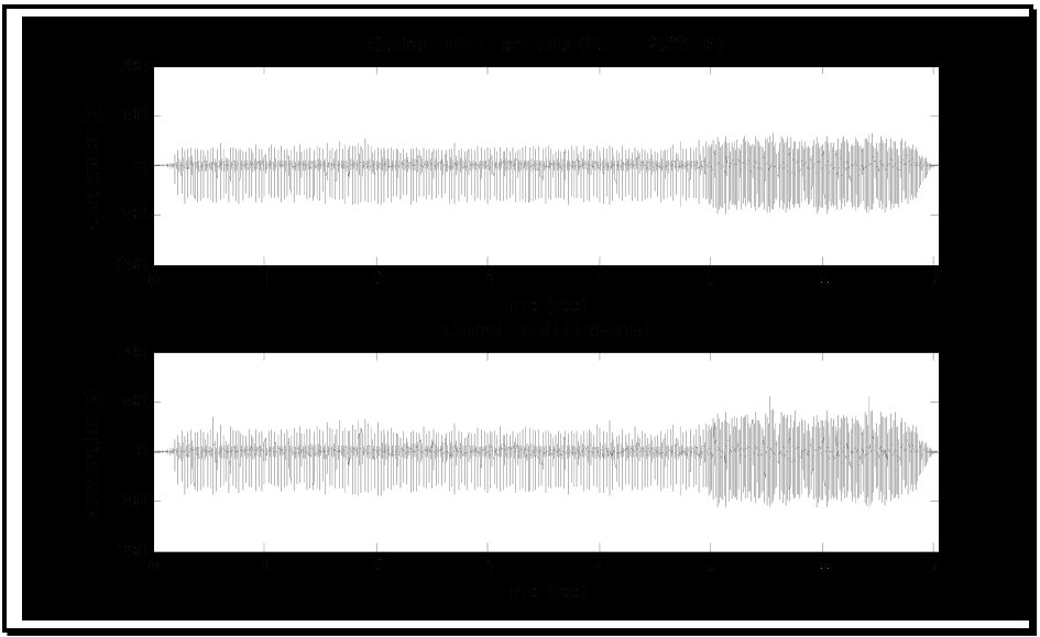
Figure description:
Vibration Analysis - Control: TWR Horizontal
Control: TWR Horizontal (10 Hz - 2000 Hz
| Time (sec) | Min Acceleration (g) | Max Acceleration (g) |
|---|---|---|
| 0.0 | 0 | 0 |
| 0.2 | -40 | 40 |
| 0.5 | -50 | 50 |
| 1.0 | -55 | 55 |
| 1.5 | -50 | 50 |
| 2.0 | -60 | 60 |
| 2.5 | -50 | 50 |
| 3.0 | -45 | 45 |
| 3.5 | -45 | 45 |
| 4.0 | -40 | 40 |
| 4.5 | -40 | 40 |
| 5.0 | -70 | 70 |
| 5.5 | -80 | 80 |
| 6.0 | -80 | 80 |
| 6.5 | -70 | 70 |
| 7.0 | 0 | 0 |
Control: TWR Horizontal
| Time (sec) | Min Acceleration (g) | Max Acceleration (g) |
|---|---|---|
| 0.0 | 0 | 0 |
| 0.2 | -50 | 50 |
| 0.5 | -60 | 60 |
| 1.0 | -75 | 75 |
| 1.5 | -65 | 65 |
| 2.0 | -60 | 60 |
| 2.5 | -55 | 55 |
| 3.0 | -60 | 60 |
| 3.5 | -55 | 55 |
| 4.0 | -55 | 55 |
| 4.5 | -50 | 50 |
| 5.0 | -85 | 85 |
| 5.2 | -110 | 110 |
| 5.5 | -120 | 120 |
| 6.0 | -115 | 115 |
| 6.5 | -95 | 95 |
| 7.0 | 0 | 0 |
Notes: The charts represent high-frequency acceleration signals over a 7-second duration. Both plots show a significant increase in signal amplitude starting around the 5-second mark. The data points in the tables represent the approximate envelope (minimum and maximum peaks of the signal at various time intervals.)
Figure 519.8A-3. Bandlimited (10 Hz to 2000 Hz) and unprocessed TWR test control time traces.
MIL-STD-810H METHOD
2.5.1 Control Options
2.5.1.1 Open/Closed Loop
For significant gunfire shock environments (and possibly benign transient vibration environments), the test for any of the procedures is typically of short duration, and is performed after appropriate compensation of the exciter analog voltage input drive waveform. Longer sequences of gunfire events may be controlled in a closed loop mode under TWR. (For example, the “real-time” control offered under TWR software). All testing is in accordance with guidelines in Method 525.2 (SESA) or Method 527.2 (MEMA). For benign gunfire environments, not considered as transient vibration, the test for any of the procedures is performed in a closed loop spectrum control in accordance with guidelines in Method 514.8 (SESA) or Method 527.2 (MEMA).
2.5.1.2 Single Point Control
Single point control SESA is a minimum requirement for all procedures. For significant gunfire shock environments, select a single point to represent the materiel fixing point from which the field-measured data were obtained, or upon which predictions are based. Tolerance specification is developed around a comparison between the “reference” time trace (measured or stochastically generated), and the “control” time trace measured in the laboratory. All testing is in accord with the guidelines of Method 525.2. For benign non-transient vibration gunfire environments, follow guidelines provided in Method 514.8 using single point spectrum control. It is highly recommended that additional measurement channels be employed in the vicinity of the control point for comparison purposes to minimize single point calibration errors.
2.5.1.3 Multiple Point Control
Where multiple axis information is available then multiple axis TWR (MEMA) may be performed where the materiel is of an extended nature, and measurements at multiple points are needed to ensure the integrity in the reproduction of the environment. All testing should be performed under the guidelines of Method 527.2 for multi-exciter testing under TWR. For benign non-transient gunfire environments, follow guidelines provided in Method 527.2 for MEMA spectrum control.
2.5.2 Control Methods
2.5.2.1 Waveform Control
Perform significant gunfire shock environment testing for all three procedures using TWR guidelines provided in Method 525.2 (SESA) or Method 527.2 (MEMA).
2.5.2.2 Spectrum Control
Benign non-transient vibration gunfire environment testing is to be performed using standard random vibration guidelines provided under Method 514.8 (SESA) or Method 527.2 (MEMA).
MIL-STD-810H METHOD 519.8
2.6 Conclusion
2.6.1 General Remarks
Procedure I defines a test rationale that provides substantial confidence in the materiel integrity under gunfire shock. In fact, for single point materiel response measurements on comparatively simple dynamic materiel, the method of direct replication of in-service measured materiel response is tailoring sensitive and near “optimal. “The main disadvantage of Procedure I is that there is no obvious way to statistically manipulate (basically “scale-up”) the measured materiel input/response data to ensure a “conservative test.” As discussed in Method 525.2, the “optimal” assumption regarding a single field measured time trace is that it represents the mean time trace or 0.5 confidence coefficient from the underlying random process it represents, i.e., if an ensemble of realizations of the underlying random process is available, the available single field measured time trace is a valid estimate of the mean of the underlying random process, or under a probabilistic framework, a single unique measured time trace must be assumed to representative of the mean of the underlying random process, assuming an infinite collection of such time traces could be collected under identical circumstances.
Procedure I is optimum when more than one measured gunfire shock environment is available, and the gunfire shock environments are concatenated into a sequence representative of the LCEP in-service conditions.
2.6.2 Stochastic Generation
In cases in which multiple gunfire replications are required from limited measurement information there exist approaches to generating stochastic time history traces. Smallwood (reference h) and Merritt (reference g) both propose pulse ensemble approaches to replication of gunfire time traces based upon measured information. Both of these procedures, Smallwood in the frequency domain and Merritt in the time domain, required that the measurement information be provided in the form of an ensemble of pulses with “correlated” time history information i.e., the ensemble of pulses were precisely “lined up” in time based upon time history correlation procedures. Both of these procedures described in detail in the references provided reliable methods for providing a stochastic generation of gunfire time trace records for laboratory testing. With the advent of “wavelet” procedures. that are localized in time, manipulation of either pulse ensemble detail wavelet coefficients or the entire measurement gunfire time trace information at some level of “wavelet detail” can be used to stochastically (as a result of wavelet coefficient manipulation) employed to generate a new gunfire shock realization that is as “close” to the measurement as desired. Wavelet coefficient manipulation because of the wavelet localization properties can be used to artificially scale measurement information to produce more conservative test scenarios. No guidelines can be provided here for implementation of wavelet based stochastic generation of time history traces, however, any stochastic manipulation and time trace reproduction under TWR must be consistent with the test tolerances provided in Methods 525.2 or 527.2.
Downloaded from https://www.everyspec.com
MIL-STD-810H
METHOD 519.8 ANNEX A
(This page is intentionally blank.)
MIL-STD-810H
METHOD 519.8 ANNEX B METHOD 519.8, ANNEX B GUIDELINES FOR PROCEDURE II - SRS GENERATED SHOCK TIME HISTORY PULSE SEQUENCE UNDER TWR