| Paragraph | Page | |
|---|---|---|
| 1. | SCOPE | 1 |
| 1.1 | PURPOSE | 1 |
| 1.2 | APPLICATION | 1 |
| 1.3 | LIMITATIONS | 1 |
| 2. | TAILORING GUIDANCE | 2 |
| 2.1 | SELECTING THE COMBINED ENVIRONMENTS METHOD | 2 |
| 2.1.1 | EFFECTS OF COMBINED TEMPERATURE/HUMIDITY/VIBRATION/ALTITUDE ENVIRONMENTS | 2 |
| 2.1.2 | SEQUENCE AMONG OTHER METHODS | 2 |
| 2.2 | SELECTING PROCEDURES | 3 |
| 2.2.1 | PROCEDURE SELECTION CONSIDERATIONS | 3 |
| 2.2.2 | DIFFERENCE AMONG PROCEDURES | 3 |
| 2.2.2.1 | PROCEDURE I – ENGINEERING DEVELOPMENT | 3 |
| 2.2.2.2 | PROCEDURE II - FLIGHT OR MISSION SUPPORT | 3 |
| 2.2.2.3 | PROCEDURE III – PLATFORM ENVELOPE | 4 |
| 2.2.3 | SELECTING COMBINED ENVIRONMENTS | 4 |
| 2.2.4 | ENVIRONMENTAL STRESSES | 4 |
| 2.2.4.1 | THERMAL STRESS | 4 |
| 2.2.4.1.1 | BAY CONDITIONS | 5 |
| 2.2.4.2 | ALTITUDE STRESS | 6 |
| 2.2.4.3 | HUMIDITY STRESS | 8 |
| 2.2.4.4 | ELECTRICAL STRESS | 8 |
| 2.2.4.4.1 | AC & DC SYSTEM NORMAL OPERATION STRESSES | 9 |
| 2.2.4.4.2 | NORMAL ON/OFF CYCLING OF MATERIAL OPERATION | 12 |
| 2.2.4.5 | VIBRATION STRESS | 12 |
| 2.3 | DETERMINE TEST LEVELS AND CONDITIONS | 14 |
| 2.3.1 | TEST CYCLE DEVELOPMENT | 14 |
| 2.4 | TEST ITEM CONFIGURATION | 17 |
| 3. | INFORMATION REQUIRED | 17 |
| 3.1 | PRETEST | 17 |
| 3.2 | DURING TEST | 17 |
| 3.3 | POST TEST | 17 |
| 4. | TEST PROCESS | 18 |
| 4.1 | TEST FACILITY | 18 |
| 4.1.1 | POWER SUPPLIES | 18 |
| 4.2 | CONTROLS | 18 |
| 4.3 | TEST INTERRUPTION | 18 |
| 4.3.1 | INTERRUPTION DUE TO FACILITY MALFUNCTION | 18 |
| 4.3.2 | INTERRUPTION DUE TO TEST ITEM OPERATION FAILURE | 18 |
| 4.3.3 | SCHEDULED INTERRUPTIONS | 19 |
| 4.4 | TEST EXECUTION | 19 |
| 4.4.1 | PREPARATION FOR TEST | 19 |
| 4.4.1.1 | PRELIMINARY STEPS | 19 |
| 4.4.1.2 | PRETEST STANDARD AMBIENT CHECKOUT | 19 |
| 4.4.2 | PROCEDURE I – ENGINEERING DEVELOPMENT | 20 |
| 4.4.3 | PROCEDURE II - FLIGHT OR MISSION SUPPORT | 20 |
| 4.4.3.1 | NON-OPERATION/GROUND SOAK | 20 |
| 4.4.3.2 | START UP/TAXI | 20 |
| 4.4.3.3 | CLIMB TO CRUISE/SURVEILLANCE | 21 |
| 4.4.3.4 | CRUISE/SURVEILLANCE | 21 |
| 4.4.3.5 | ATTACK | 22 |
| 4.4.3.6 | DESCENT/LANDING | 22 |
| 4.4.3.7 | MAINTENANCE | 23 |
| 4.4.4 | PROCEDURE III - PLATFORM ENVELOPE | 25 |
| 4.4.4.1 | PROCEDURE III - STEPS | 33 |
| 5. | ANALYSIS OF RESULTS | 37 |
| 5.1 | Analysis of Test Results | 37 |
| 5.2 | Analysis of Failures | 37 |
| 6. | REFERENCE/RELATED DOCUMENTS | 37 |
| 6.1 | REFERENCED DOCUMENTS | 37 |
| 6.2 | RELATED DOCUMENTS | 38 |
FIGURES
| FIGURE 520.5-1. | TEST PROFILE GENERATION FLOW DIAGRAM | 16 |
| FIGURE 520.5-2. | PROCEDURE II- PROFILE NOTIONAL EXAMPLE | 24 |
| FIGURE 520.5-3A. | PROCEDURE III- PLATFORM ENVELOPE OPTION 1EXAMPLE | 31 |
| FIGURE 520.5-3B | PROCEDURE III-PLATFORM ENVELOPE OPTION 2 EXAMPLE | 32 |
| FIGURE 520.5A-1. | SCHEMATIC MISSION PROFILE, ALTITUDE, AND MACH NUMBER | A-1 |
TABLES
| TABLE 520.5-I. | TYPICAL SUPPLEMENTAL COOLING AIR PARAMETERS, F-15 PLATFORM LCEP EXAMPLE. | 6 |
| TABLE 520.5-II. | PRESSURE VS ALTITUDE CONVERSION EQUATIONS | 7 |
| TABLE 520.5-III. | INPUT VOLTAGE AND FREQUENCY TEST SCHEDULE | 9 |
| TABLE 520.5-IV. | AIRCRAFT ELECTRICAL POWER CHARACTERISTICS | 10 |
| TABLE 520.5-V | GROUND VEHICLE 28 VDC CHARACTERISTICS | 11 |
| TABLE 520.5-VI. | RTCA DO-160 POWER CHARACTERISTICS | 11 |
| TABLE 520.5-VII. | DEFAULT FUNCTIONAL VIBRATION TEST CRITERIA | 13 |
| TABLE 520.5-VIII. | TEST PARAMETER SELECTION/PROFILE DEVELOPMENT | 15 |
| TABLE 520.5-IX. | PROCEDURE I AND III - TEST CYCLE TEMPLATE. | 26 |
| TABLE 520.5A-I. | AMBIENT OUTSIDE AIR TEMPERATURES (HOT ATMOSPHERE MODEL) | A-2 |
| TABLE 520.5A-II. | AMBIENT OUTSIDE AIR TEMPERATURES (COLD ATMOSPHERE MODEL) | A-2 |
| TABLE 520.5A -II. | AMBIENT OUTSIDE AIR TEMPERATURES (WARM MOIST ATMOSPHERE MODEL) | A-3 |
MIL-STD-810H METHOD
520.5 METHOD
520.5 COMBINED ENVIRONMENTS
NOTE: The example profiles provided in this method do not represent specific platform/mission scenarios and are not to be used as default profiles. Tailoring is essential. Select methods, procedures, and parameter levels based on the tailoring process described in Part One, paragraph 4.2.2, and Annex C. Apply the general guidelines for laboratory test methods described in Part One, paragraph 5 of this standard.
Due to extensive revision to this method, no change bars have been provided.
520.5 Table 520.5-V. Ground Vehicle
520.5 Table 520.5-VII. Default Functional Vibration Test Criteria
| Aircraft Type | Default Vibration Profiles | Notes Regarding Default Vibration Profiles |
|---|---|---|
| Fixed Wing Jet Aircraft | Method 514, Table 514.8 D-I | As stated in Method 514, Annex D, default vibration profiles for fixed wing jet aircraft are based on empirical data and time compression information is unknown. The vibration profile should be computed for each segment of the mission profile. Functional vibration tests should be conducted at the amplitudes computed from Table 514.8-D-I for sufficient time to fully verify equipment functionality. |
| Fixed Wing Propeller Aircraft | Method 514, Tables 514.8 D-II | As stated in Method 514, Annex D, Paragraph 2.2d, default functional test vibration levels for fixed wing propeller aircraft can be derived by scaling the endurance ASD levels described in Table 514.8D-II. |
| Helicopters | Method 514, Tables 514.8D-III | As stated in Method 514, Annex D, Paragraph 2.3e(4), default functional test vibration levels for helicopters can be derived by scaling the endurance levels described in Table 514.8D-III. |
- e. If it is determined that the synergistic effects of vibration/altitude or vibration/humidity have little or no impact on the performance of the materiel, vibration may be applied combined with temperature as part of vibration testing (Method 514), with temperature, altitude, and humidity environments combined separately.
- i. Short duration vibration or shock events and those that occur infrequently in the test cycle should be considered in addition to steady state vibration described in Method 514. If the synergistic effects of these events with altitude or humidity are determined to have significant impact on the performance of the materiel. Typical transient events on fixed and rotary wing aircraft may include firing of on-board guns, opening of bomb-bay doors, launcher ejection, adjacent missile launches, and shock due to hard landings. If the synergistic effects of these events are not significant, test for these events separately, or combined with temperature, using the appropriate test method within this Standard.
- j. For those segments with similar vibration spectrum shape, use the following analysis to reduce the number of vibration test levels. The discussion is in terms of the suggested spectrum shapes for jet, rotary wing, or propeller aircraft of Method 514.
- (1) Determine the vibration level, Wo (g2/Hz), for each mission segment using the altitude and Mach number plots for each mission.
NOTE: For test purposes, the larger Wo due to aerodynamic forces or Wo due to jet engine noise, etc., is used at any point in time in the mission. Identify the maximum Wo value that occurs in each mission.
- (2) Consider all segments of the mission that have values within three dB of maximum, as having a constant value of . Consider all segments of the mission that have values between and as having a constant value of . This process of identifying three-dB bands of dynamic vibration values, over which is considered to be a constant and whose value is determined by using the dynamic vibration value of the band's midpoint, is continued until the calculated value is less than . For test purposes, segments of the mission with calculated values of less than can be set equal to 0.001 . Each segment has a respective time in mission
associated with it that is added together creating a T(MAX), T(-4.5), etc. Vibration is then applied for their respective times during the test. A single vibration level may be created using the test acceleration formula of Method 514, Annex A, paragraph 2.2, but the synergistic effects in combination with temperature may be misapplied.
520.5 Table 520.5-VIII: Test Parameter Selection/Profile Development
| Procedure | Step | Task | ||
|---|---|---|---|---|
| I | II | III | ||
| X | X | X | Step 1 | Identify the platform(s), the test materiel installation location(s), and geographical deployment location(s). |
| X | X | Step 2 | Identify the platform(s)/materiel specification requirements. Specification requirements should encompass all planned mission requirements. | |
| X | Step 2a | Identify the specific mission scenario(s). | ||
| X | X | Step 3 | Identify applicable individual forcing functions (temperature, altitude, humidity, input electrical power, functional vibration , etc.) (Exception: short term and transient events, e.g., gunfire, crash shock, etc.) | |
| X | Step 3a | Identify the specific mission forcing functions that support the mission profile. (including climatic, dynamic, and electrical functions) | ||
| X | X | X | Step 4 | Identify operational requirements of the equipment, including duty cycle, transients, and operational modes (to include all anticipated mission operational scenarios) |
| X | X | X | Step 5 | Identify the temperature, altitude, humidity, input electrical power, and functional vibration levels for each segment of the test profile. See para 2.2.4 and sub paragraphs. |
| X | X | X | Step 6 | Identify the type of cooling (RAM/ECS/convective) and cooling environment for the test item for each segment (see paragraph 2.2.4.1 and 2.2.4.1.1). |
| X | X | X | Step 7 | Develop a table listing all the applicable forcing functions/levels and operational requirements identified in the above steps for each mission or platform. |
| X | X | Step 8 | Identify the applicable combinations of climatic/dynamic/ power parameters considering the full range of platform requirements, as derived from the LCEP. This should include all anticipated combinations of thermal/altitude/humidity/vibration environment and the associated operational/power requirements for each segment of the test profile. For high performance aircraft the Mach/altitude effects shall be considered. | |
| X | Step 8a | Identify the thermal/altitude/humidity/vibration environment combinations and the associated operational/power requirements for each mission segment (start, idle, taxi, take off, climb, cruise, loiter, combat, maneuver, descent landing). | ||
| X | X | Step 9 | Using the data identified in steps 1 through 8, develop a representative composite table/profile for thermal, altitude, humidity, functional vibration, test item cooling, and operational power for the most severe expected environments. (see Table 520.5-IX and Figures 520.5-3a and 520.3b) | |
| X | Step 9a | Using the data identified in steps 1 through 8, develop a thermal, altitude, humidity, functional vibration, test item cooling and operational power profile. | ||
MIL-STD-810H
METHOD 520.5
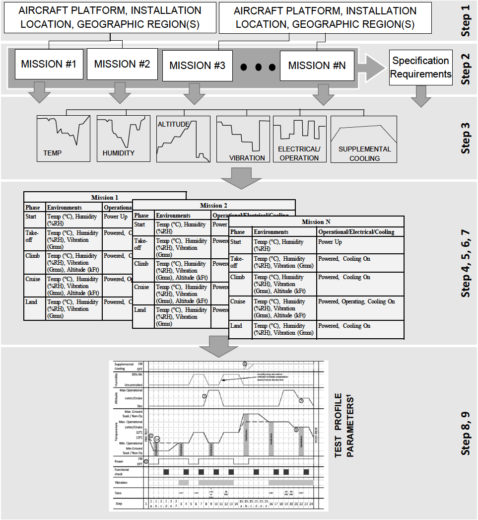
Figure description:
AIRCRAFT EQUIPMENT TEST PROFILE DEVELOPMENT FLOWCHART Steps 1 through 9: Development Process and Resulting Detailed Profile
Representative Mission Environmental and Operational Phases (Missions 1 through N
| Phase | Environments | Operational/Electrical/Cooling |
|---|---|---|
| Start | Temp (°C, Humidity (%RH)) | Power Up |
| Take-off | Temp (°C, Humidity (%RH, Vibration (Grms))) | Powered, Cooling On |
| Climb | Temp (°C, Humidity (%RH, Vibration (Grms, Altitude (kFt)))) | Powered, Cooling On |
| Cruise | Temp (°C, Humidity (%RH, Vibration (Grms, Altitude (kFt)))) | Powered, Operating, Cooling On |
| Land | Temp (°C, Humidity (%RH, Vibration (Grms))) | Powered, Cooling On |
TEST PROFILE PARAMETERS¹
Annotations
- 1 (text_label - position: Temperature curve at Step 2a)
- 2 (text_label - position: Altitude curve rising at Step 7)
- 3,4 (text_label - position: Temperature curve rising at Step 2c-d)
- 5 (text_label - position: Power switching ON at Step 2e)
- 6 (text_label - position: Supplemental Cooling switching ON at Step 15e)
- 7 (text_label - position: Altitude curve falling at Step 10)
- 8 (text_label - position: Temperature curve falling at Step 21)
- Humidity ramp rate shall be sufficient to indicate condensation and/or frost on the test item. (text_label - position: Humidity chart section)
| Step | Time | Temperature | Altitude | Humidity | Power | Supplemental Cooling | Functional Check | Vibration |
|---|---|---|---|---|---|---|---|---|
| 1 | PRE-TEST | 23°C | Site | Uncontrolled | OFF | OFF | OFF | OFF |
| 2a | Stabilization | Falling to Min Ground Soak | Site | Uncontrolled | OFF | OFF | OFF | OFF |
| 2b | Stabilization | Min Ground Soak / Non-Op | Site | Uncontrolled | OFF | OFF | OFF | OFF |
| 2c | Stabilization | Rising to Min Operational | Site | Uncontrolled | OFF | OFF | OFF | OFF |
| 2d | Stabilization | Min Operational | Site | Uncontrolled | OFF | OFF | OFF | OFF |
| 2e | Stabilization | Min Operational | Site | Uncontrolled | ON | OFF | OFF | OFF |
| 2f | Stabilization | Min Operational | Site | Uncontrolled | ON | OFF | OFF | OFF |
| 3 | 2 hr | Min Operational | Site | Uncontrolled | ON | OFF | OFF | Low |
| 4 | - | Rising to 23°C | Site | Uncontrolled | ON | OFF | OFF | OFF |
| 5 | 1 hr | 23°C | Site | Uncontrolled | ON | OFF | ON | OFF |
| 6 | - | Rising to 32°C | Site | Uncontrolled | ON | OFF | OFF | OFF |
| 7 | 1 hr | 32°C | Loiter/Cruise | Uncontrolled | ON | OFF | OFF | Low |
| 8 | - | Rising to Max Operational | Max Operational | Uncontrolled | ON | OFF | OFF | OFF |
| 9 | 30 min | Max Operational | Max Operational | 95% RH | ON | OFF | OFF | High |
| 10 | - | Falling to 32°C | Loiter/Cruise | Ramping Down | ON | OFF | OFF | OFF |
| 11 | 1 hr | 32°C | Loiter/Cruise | Uncontrolled | ON | OFF | OFF | Low |
| 12 | - | Falling to 23°C | Site | Uncontrolled | ON | OFF | OFF | OFF |
| 13 | 15 min | 23°C | Site | Uncontrolled | ON | OFF | OFF | OFF |
| 14 | - | 23°C | Site | Uncontrolled | ON | OFF | ON | OFF |
| 15a | Stabilization | Rising to Max Operational | Site | Uncontrolled | ON | OFF | OFF | OFF |
| 15b | Stabilization | Max Operational | Site | Uncontrolled | ON | OFF | OFF | OFF |
| 15c | Stabilization | Rising to Max Ground Soak | Site | Uncontrolled | ON | OFF | OFF | OFF |
| 15d | Stabilization | Max Ground Soak / Non-Op | Site | Uncontrolled | ON | OFF | OFF | OFF |
| 15e | Stabilization | Falling to Max Operational | Site | Uncontrolled | ON | ON | OFF | OFF |
| 15f | Stabilization | Max Operational | Site | Uncontrolled | ON | ON | OFF | OFF |
| 16 | - | Max Operational | Site | Uncontrolled | ON | ON | OFF | OFF |
| 17 | 2 hr | Max Operational | Site | Uncontrolled | ON | ON | OFF | Low |
| 18 | - | Max Operational | Site | Uncontrolled | ON | ON | OFF | OFF |
| 19 | - | Falling to 32°C | Site | Uncontrolled | ON | ON | OFF | OFF |
| 20 | 15 min / 45 min | 32°C | Site | Uncontrolled | ON | ON | ON | OFF |
| 21 | - | Falling to 23°C | Site | Uncontrolled | ON | ON | OFF | OFF |
| 22 | 2 hr | 23°C | Site | Uncontrolled | ON | ON | OFF | Low |
| 23 | - | 23°C | Site | Uncontrolled | OFF | OFF | OFF | OFF |
| 24 | POST-TEST | 23°C | Site | Uncontrolled | OFF | OFF | OFF | OFF |
Notes: The flowchart details the step-by-step process of deriving complex environmental test profiles. Step 3 introduces standard profile shapes for temperature, humidity, altitude, vibration, electrical/operation, and supplemental cooling. Steps 4-7 organize these into mission-specific phase tables. Steps 8-9 aggregate all data into a unified test profile. Note: Steps 2a-f and 15a-f are designated as 'Stabilization' periods.
Note 1: Procedure II utilizes data from Single Mission or Subset of Missions, while Procedures I and III utilize data from the entire life cycle of missions.
Figure 520.5-1. Test profile generation flow diagram
MIL-STD-810H
METHOD 520.5
520.5 Table 520.5-IX (Con't) Template: Procedure I and III - Envelope test cycle (Based on Option 1)
The following table correlates to the profile steps and typical mission segments. This template shall be populated with actual parameters derived from Table 520.5-VIII. Reference Paragraph 2.3.1, Table 520.5-VIII, Step 9
| STEP | Test Phase Definition | Temp °C (°F) | Relative Humidity | Supp. Cooling Air °C (°F) | Supp. Cooling Mass Flow (lbs/min) | Altitude | Test Item- Operating/non op. | Func Test | Duration |
|---|---|---|---|---|---|---|---|---|---|
| 19 | Hot/Dry High Altitude Functional test | Max Op Temp | <10% | Per Spec | Mass Flow adjusted for Alt | Max Op Alt | Operating | Yes | 15 minutes minimum |
| 20 | Ramp to Loiter/Cruise Temp | Ramp (Max Op Temp to Cruise Op Temp) (Note 6) | <10% | Per Spec | Mass Flow adjusted for Alt | Max Op Alt | Operating | No | 45 minutes minimum |
| 21 | Loiter/Cruise Altitude Ramp | Cruise Op Temp (Note 6) | <10% | Per Spec | Ramp (Adjust Mass Flow for Cruise Alt) | Ramp to Cruise Alt (Note 5) | Operating | No | As Required |
| 22 | Hot/Dry Loiter/Cruise Soak | Cruise Op Temp | <10% | Per Spec | Mass Flow adjusted for Cruise Alt | Cruise Alt (Note 7) | Operating | No | 3 hours minimum |
| 23 | Hot/Dry Loiter/Cruise Functional test | Cruise Op Temp | <10% | Per Spec | Mass Flow adjusted for Cruise Alt | Cruise Alt (Note 7) | Operating | Yes | As Required |
| 24 | Ramp to Site Ambient | Ramp to ambient (Note 2) | <10% | Per Spec | Per Spec | Ramp to Site (Note 5) | Operating/Non-Operating | No | As Required |
| 25 | Repeat Steps 2 thru 24 as required |
Table 520.5-IX (Con't) Template: Procedure I and III - Envelope test cycle (Based on Option 1)
The following table correlates to the profile steps and typical mission segments. This template shall be populated with actual parameters derived from Table 520.5-VIII. Reference Paragraph 2.3.1, Table 520.5-VIII, Step 9
| STEP | Test Phase Definition | Temp °C (°F) | Relative Humidity | Supp. Cooling Air °C (°F) | Supp. Cooling Mass Flow (lbs/min) | Altitude | Test Item- Operating/non op. | Func Test | Duration |
|---|---|---|---|---|---|---|---|---|---|
| 26 | Post Functional Test | Standard Ambient | Uncontrolled | Off | OFF | Site | Operating/Non- operating | Yes | Minimum Time required Post Test and power down |
Table 520.4-IX Notes:
- Temperature parameters shall be the extreme platform envelope values for the test condition.
- Temperature Ramp Rate: LAW equip specification. If not specified, then ≤5 Deg C/min.
- Stabilization:
Non-Operational Equipment: See Part One, paragraph 5.4.2
Operational Equipment: See Part One, paragraph 5.4.1
- Altitude parameters shall be maximum platform envelope values for the test condition.
- Altitude Ramp Rate: IAW equipment specification.
- Loiter/Cruise Op Temp: Localized ambient air temp with inflight atmospheric cooling effects. IAW Platform guidance. If guidance is not provided, use the maximum operational temperature.
- Loiter/Cruise Altitude: As determined by the Program Office. This shall represent a typical long duration cruise altitude. If guidance is not provided, use the maximum operational altitude.
- Input Electrical Power:
- a. Voltage; Alternate from cycle to cycle; Nominal, High, Low, High, etc. See Tables 520.5-III, IV, V, and VI for guidance.
- b. Frequency Variation: The input electrical power frequency shall be varied from cycle to cycle. See Tables 520.5-III, V, and VI for guidance.
- Supplemental Cooling temperature and mass flow rate shall be IAW the platform/system specification. There shall be no ECS supplemental cooling for the first 2 minutes following power on.
- This shall be followed by a linear drop in the ECS supplemental cooling air temperature to the specified cooling temperature. The ECS cooling air temperature ramp rate shall be determined from the platform ECS specification. For RAM cooled compartment a thermal analysis shall be performed per the guidance in paragraph 2.2.4.1.1.a.
- It is permissible to delay the humidity ramp until the chamber temperature reaches 0 C.
- Vibration is an integral part of the flight environment. Although not shown on the above table, when added to the test the vibration levels shall be representative of the functional vibration levels for the specific phase of the mission.
MIL-STD-810H
METHOD 520.5
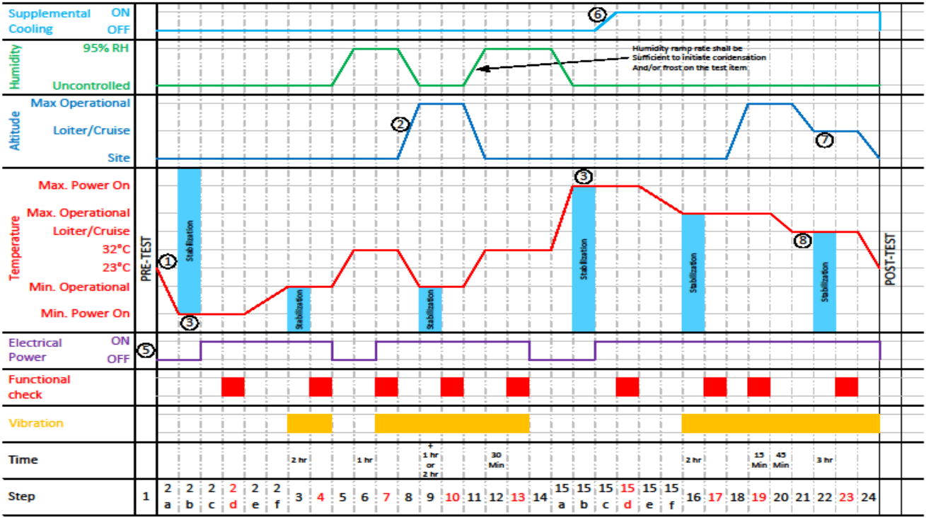
Figure description:
Comprehensive Environmental Test Profile Graph
Environmental Test Profile
Legend
- Supplemental Cooling — color: cyan; symbol: Solid line
- Humidity — color: green; symbol: Solid line
- Altitude — color: blue; symbol: Solid line
- Temperature — color: red; symbol: Solid line
- Electrical Power — color: purple; symbol: Solid line
- Functional check — color: red; symbol: Solid bar
- Vibration — color: yellow; symbol: Solid bar
- Stabilization — color: light blue; symbol: Shaded region
Annotations
- 1 (text_label - position: Start of temperature ramp profile)
- 2 (text_label - position: Altitude ramp up to Max Operational)
- 3 (shaded_area - position: Indicates stabilization periods marked with light blue shading)
- 5 (text_label - position: Electrical Power profile line)
- 6 (text_label - position: Supplemental Cooling ramp from OFF to ON)
- 7 (text_label - position: Altitude ramp down to Site level)
- 8 (text_label - position: Temperature stabilization at 23°C)
- Humidity Note (text_label - position: Humidity ramp rate shall be sufficient to initiate condensation And/or frost on the test item)
| Step | Time (Duration) | Supplemental Cooling | Humidity | Altitude | Temperature | Electrical Power | Functional check | Vibration |
|---|---|---|---|---|---|---|---|---|
| 1 | OFF | Uncontrolled | Site | ~23°C (ambient) | OFF | No | No | |
| 2a | OFF | Uncontrolled | Site | Ramp to Min. Power On | OFF | No | No | |
| 2b | OFF | Uncontrolled | Site | Min. Power On (Stabilization) | ON | No | No | |
| 2c | OFF | Uncontrolled | Site | Min. Power On | ON | No | No | |
| 2d | OFF | Uncontrolled | Site | Min. Power On | ON | Yes | No | |
| 2e | OFF | Uncontrolled | Site | Min. Power On | ON | No | No | |
| 2f | OFF | Uncontrolled | Site | Min. Power On | ON | No | No | |
| 3 | 2 hr | OFF | Uncontrolled | Site | Ramp to Min. Operational (Stabilization) | ON | No | Yes |
| 4 | OFF | Uncontrolled | Site | Min. Operational | ON | Yes | Yes | |
| 5 | OFF | Uncontrolled | Site | Ramp to 23°C | ON | No | No | |
| 6 | 1 hr | OFF | Uncontrolled | Site | 23°C | ON -> OFF | No | No |
| 7 | OFF | Ramp to 95% RH | Site | Ramp to 32°C | OFF -> ON | No | No | |
| 8 | OFF | 95% RH | Site | 32°C | ON | Yes | Yes | |
| 9 | 1 hr or 2 hr | OFF | Ramp to Uncontrolled | Ramp to Max Operational | Ramp to Min. Operational (Stabilization) | ON | No | Yes |
| 10 | OFF | Uncontrolled | Max Operational | Min. Operational | ON | Yes | Yes | |
| 11 | OFF | Ramp to 95% RH | Ramp to Site | Ramp to 32°C | ON -> OFF | No | Yes | |
| 12 | 30 Min | OFF | 95% RH | Site | 32°C | OFF -> ON | No | Yes |
| 13 | OFF | Ramp to Uncontrolled | Site | Ramp to Max Power On | ON | Yes | Yes | |
| 14 | OFF | Uncontrolled | Site | Max Power On to Max Operational | OFF | No | No | |
| 15a | OFF | Uncontrolled | Site | Max Operational | OFF | No | No | |
| 15b | Ramp to ON | Uncontrolled | Site | Max Operational (Stabilization) | ON | No | No | |
| 15c | ON | Uncontrolled | Site | Max Operational | ON | No | No | |
| 15d | ON | Uncontrolled | Site | Max Operational | ON | Yes | No | |
| 15e | ON | Uncontrolled | Site | Max Operational | ON | No | No | |
| 15f | ON | Uncontrolled | Site | Max Operational | ON | No | No | |
| 16 | 2 hr | ON | Uncontrolled | Site | Ramp to Loiter/Cruise (Stabilization) | ON | No | Yes |
| 17 | ON | Uncontrolled | Site | Loiter/Cruise | ON | Yes | Yes | |
| 18 | ON | Uncontrolled | Ramp to Max Operational | Ramp to 32°C | ON | No | Yes | |
| 19 | 15 Min | ON | Uncontrolled | Max Operational | 32°C | ON | Yes | Yes |
| 20 | 45 Min | ON | Uncontrolled | Ramp to Loiter/Cruise | Ramp to 23°C | ON | No | Yes |
| 21 | ON | Uncontrolled | Loiter/Cruise | 23°C | ON | No | Yes | |
| 22 | 3 hr | ON | Uncontrolled | Ramp to Site | 23°C (Stabilization) | ON | No | Yes |
| 23 | ON | Uncontrolled | Site | 23°C | ON | Yes | Yes | |
| 24 | ON | Uncontrolled | Site | Ramp down | ON | No | Yes |
Figure 520.5-3a. Platform Envelope Option 1 Profile Example (See notes for additional information.)
MIL-STD-810H
METHOD 520.5
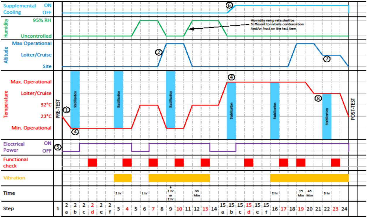
Figure description:
Environmental Test Profile Chart
Environmental Test Profile
Legend
- Supplemental Cooling — color: light blue; symbol: Solid line
- Humidity — color: green; symbol: Solid line
- Altitude — color: blue; symbol: Solid line
- Temperature — color: red; symbol: Solid line
- Electrical Power — color: purple; symbol: Solid line
- Functional check — color: red; symbol: Solid block
- Vibration — color: orange; symbol: Solid block
- Stabilization — color: cyan; symbol: Shaded vertical area
Annotations
- (1 (text_label - position: Step 2a: Temperature start of ramp down))
- (2 (text_label - position: Step 7: Altitude start of ramp up))
- (3 Humidity ramp rate shall be sufficient to initiate condensation And/or frost on the test item (text_label - position: Steps 5 and 10 humidity ramps))
- (4 Stabilization (shaded_area - position: Steps 2, 5, 9, 15, 22))
- (5 (text_label - position: Electrical Power start))
- (6 (text_label - position: Step 15: Supplemental Cooling start of ramp up))
- (7 (text_label - position: Step 20: Altitude start of ramp down))
- (8 (text_label - position: Step 20: Temperature start of ramp down))
| Step | Supplemental Cooling | Humidity | Altitude | Temperature | Electrical Power | Functional check | Vibration | Time |
|---|---|---|---|---|---|---|---|---|
| 1 | OFF | Uncontrolled | Site | 23°C | OFF | Inactive | Inactive | |
| 2a | OFF | Uncontrolled | Site | Ramp to Min. Operational | OFF | Inactive | Inactive | |
| 2b | OFF | Uncontrolled | Site | Min. Operational | ON | Inactive | Inactive | |
| 2c | OFF | Uncontrolled | Site | Min. Operational | ON | Inactive | Inactive | |
| 2d | OFF | Uncontrolled | Site | Min. Operational | ON | Active | Inactive | |
| 2e | OFF | Uncontrolled | Site | Min. Operational | ON | Inactive | Inactive | |
| 2f | OFF | Uncontrolled | Site | Min. Operational | ON | Inactive | Inactive | |
| 3 | OFF | Uncontrolled | Site | Min. Operational | ON | Inactive | Active | 2 hr |
| 4 | OFF | Uncontrolled | Site | Min. Operational | ON | Active | Active | |
| 5 | OFF | Ramp to 95% RH | Site | Ramp to 32°C | OFF | Inactive | Inactive | |
| 6 | OFF | 95% RH | Site | 32°C | OFF | Active | Inactive | 1 hr |
| 7 | OFF | 95% RH | Ramp to Max Operational | 32°C | ON | Inactive | Active | |
| 8 | OFF | Ramp to Uncontrolled | Max Operational | Ramp to Min. Operational | ON | Inactive | Active | |
| 9 | OFF | Uncontrolled | Max Operational | Min. Operational | ON | Active | Active | + 1 hr or 2 hr |
| 10 | OFF | Ramp to 95% RH | Ramp to Site | Ramp to 32°C | ON | Inactive | Active | |
| 11 | OFF | 95% RH | Site | 32°C | ON | Active | Active | 30 Min |
| 12 | OFF | Ramp to Uncontrolled | Site | 32°C | ON | Inactive | Active | |
| 13 | OFF | Uncontrolled | Site | 32°C | OFF | Active | Active | |
| 14 | OFF | Uncontrolled | Site | Ramp to Max. Operational | OFF | Inactive | Inactive | |
| 15a | Ramp to ON | Uncontrolled | Site | Max. Operational | OFF | Inactive | Inactive | |
| 15b | ON | Uncontrolled | Site | Max. Operational | ON | Inactive | Inactive | |
| 15c | ON | Uncontrolled | Site | Max. Operational | ON | Inactive | Inactive | |
| 15d | ON | Uncontrolled | Site | Max. Operational | ON | Active | Inactive | |
| 15e | ON | Uncontrolled | Site | Max. Operational | ON | Inactive | Inactive | |
| 15f | ON | Uncontrolled | Site | Max. Operational | ON | Inactive | Inactive | |
| 16 | ON | Uncontrolled | Site | Max. Operational | ON | Inactive | Active | 2 hr |
| 17 | ON | Uncontrolled | Site | Max. Operational | ON | Active | Active | |
| 18 | ON | Uncontrolled | Ramp to Max Operational | Max. Operational | ON | Inactive | Active | |
| 19 | ON | Uncontrolled | Max Operational | Max. Operational | ON | Active | Active | 15 Min |
| 20 | ON | Uncontrolled | Ramp to Loiter/Cruise | Ramp to Loiter/Cruise | ON | Inactive | Active | 45 Min |
| 21 | ON | Uncontrolled | Loiter/Cruise | Loiter/Cruise | ON | Inactive | Active | |
| 22 | ON | Uncontrolled | Loiter/Cruise | Loiter/Cruise | ON | Inactive | Active | 3 hr |
| 23 | ON | Uncontrolled | Loiter/Cruise | Loiter/Cruise | ON | Active | Active | |
| 24 | ON | Uncontrolled | Ramp to Site | Ramp to 23°C | ON | Inactive | Active | |
| POST-TEST | ON | Uncontrolled | Site | 23°C | ON | Inactive | Inactive |
Notes: The chart represents a comprehensive environmental test profile including temperature, humidity, altitude, vibration, and electrical power states across 24 defined steps plus pre- and post-test phases.
Figure 520.5-3b. Platform Envelope Option 2 Profile Example (See notes for additional information.)
Figures 520.5-3a and 520-3b. Notes:
- Temperature Ramp Rate: IAW equipment or platform(s) specification. If not specified then <5 Deg C/min.
- Altitude Ramp Rate: IAW equipment or platform(s) specification.
- Altitude Ramp Rate: HLV equipment or platform(s) specification.
- Option 1 applies materiel which, during its life cycle, is expected to be powered "ON" at temperatures either less than or greater than the normal operational temperature. This includes materiel that is powered "ON" concurrent with aircraft startup or that is powered "ON" while the aircraft is on the tarmac in a thermally ground soaked condition. Unless otherwise specified, the minimum and maximum start up temperatures will generally equate to the minimum and maximum ground soak temperatures (Figure 520.5-3a).
- Option 2 applies to materiel which is powered “ON” during flight operations after the aircraft temperature has stabilized at its normal operational temperature. (Figure 520.5-3b)
- Input Electrical Power:
a.
- Voltage: Alternate from cycle to cycle; Nominal, High, Low, High, etc. See Tables 520.5-III, IV, V, and VI for guidance.
- a. Voltage: Alternate from cycle to cycle, Nominal, High, Low, High, etc. See Tables 520.5-III, IV, V, and VI for guidance. b. Frequency Variation: The input electrical power frequency shall be varied from cycle to cycle. . See Tables 520.5-III, V, and VI for guidance.
Note: Flight critical equipment may be required to operate under abnormal and/or emergency voltage condition. See Table IV and MIL-STD-704 for the appropriate levels. See paragraph 2 2.4.4. for additional guidance.
- Supplemental Cooling temperature and mass flow rate shall be IAW the platform/system specification. There shall be no ECS supplemental cooling for the first 2 minutes following power on. This shall be followed by a linear drop in the ECS supplemental cooling air temperature to the specified cooling temperature. The ECS cooling air temperature ramp rate shall be determined from the platform ECS specification. For RAM cooled compartment a thermal analysis shall be performed per the guidance in paragraph 2.2.4.1.1.a.
- Loiter Altitude: IAW Platform guidance. If guidance is not provided, use the maximum operational altitude.
- Loiter Altitude: IAW Platform guidance. If guidance is not provided, use the maximum operational altitude.
- Loiter Temperature: IAW Platform guidance and location of equipment. If guidance is not provided, use the maximum operational temperature.
- Vibration may be performed separately with temperature. Vibration is intended to be tailored for the test items specific rotorcraft and/or fixed wing application and the levels should be in accordance with the levels expected during the specific mission segments.
- It is preferred that consecutive cycles be run continuously; however, if test chamber operations preclude continuous operation, then the transition from high altitude to site, and from loiter temperature to minimum temperature shall be completed prior to interrupting the cycles. These conditions shall be maintained until the cycle is resumed.
- Pre-Test, Post-test and Functional tests are performed to verify consistent satisfactory performance throughout the test. Pre and Post tests are generally the same. Functional tests, especially during altitude exposure, may be dependent on chamber access. These tests should be tailored per guidance in Part One.
- For External stores/munitions the solar equivalent temperature may be used to determine the high altitude temperature parameters. Referenced JOTP-012.
- Humidity: The humidity ramp rate for steps 5, 8, and 15A shall track the temperature ramp. The humidity ramp rate for step 11 shall be sufficient to initiate condensation and/or frost on the test item.
520.5 ANNEX A METHOD 520.5, ANNEX A Supplemental Tailoring Guidance
An individual platform is designed to operate within a set of specified operating mission envelopes (Mach number/altitude regime) and profiles (see Figure 520.5A-1). For example, an aircraft can fly many different missions such as training, air superiority, interdiction, ground support, etc. Often, high-threat combat will generate more extreme environments; such as increased temperature effects, dynamic pressures, vibration, condensation, etc. Reference Method 514, Annex A, paragraph 2.6.
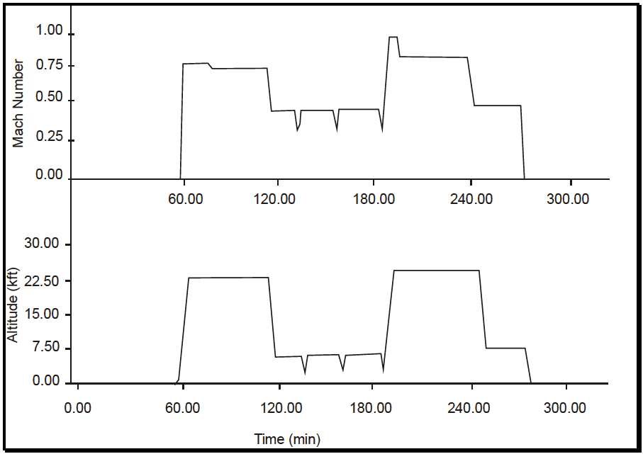
Figure description:
Flight Profile: Mach Number and Altitude vs Time
Mach Number
| Time (min) | Mach Number |
|---|---|
| 0.00 | 0.00 |
| 58.00 | 0.00 |
| 60.00 | 0.78 |
| 75.00 | 0.78 |
| 77.00 | 0.74 |
| 113.00 | 0.74 |
| 117.00 | 0.45 |
| 133.00 | 0.45 |
| 135.00 | 0.30 |
| 137.00 | 0.45 |
| 158.00 | 0.45 |
| 160.00 | 0.30 |
| 162.00 | 0.45 |
| 183.00 | 0.45 |
| 185.00 | 0.30 |
| 187.00 | 0.45 |
| 190.00 | 0.98 |
| 195.00 | 0.98 |
| 197.00 | 0.83 |
| 238.00 | 0.83 |
| 242.00 | 0.48 |
| 272.00 | 0.48 |
| 275.00 | 0.00 |
| 300.00 | 0.00 |
Altitude (kft
| Time (min) | Altitude (kft) |
|---|---|
| 0.00 | 0.00 |
| 58.00 | 0.00 |
| 64.00 | 23.50 |
| 113.00 | 23.50 |
| 118.00 | 5.50 |
| 133.00 | 5.50 |
| 135.00 | 2.00 |
| 137.00 | 5.50 |
| 158.00 | 5.50 |
| 160.00 | 2.00 |
| 162.00 | 5.50 |
| 183.00 | 5.50 |
| 185.00 | 2.00 |
| 187.00 | 5.50 |
| 195.00 | 25.00 |
| 245.00 | 25.00 |
| 250.00 | 7.50 |
| 272.00 | 7.50 |
| 275.00 | 0.00 |
| 300.00 | 0.00 |
Notes: The figure consists of two aligned subplots sharing a common Time (min x-axis. The top chart shows Mach Number over time, and the bottom chart shows Altitude in kilofeet (kft over time.))
Figure 520.5A-1. Schematic mission profile, altitude, and Mach number (F-15 ground attack example).
MIL-STD-810H METHOD
520.5 ANNEX A
The Standard Atmospheric Models presented in Tables 520.5A-I thru 520.5A-III may be used in determining the altitude, temperature, relative humidity, and dew point correlations when specific flight data is not available. Reference paragraphs 2.2.4.2 (Altitude Stress) and 2.2.4.3 (Humidity Stress).
| Altitude | World-Wide Air Operations | Relative Humidity (%) | Dew Temperature | |||
|---|---|---|---|---|---|---|
| km | kft | °C | °F | °C | °F | |
| 0 | 0.00 | 43 | 109 | <10 | 4 | 40 |
| 1 | 3.28 | 34 | 93 | <10 | -2 | 29 |
| 2 | 6.56 | 27 | 81 | <10 | -6 | 21 |
| 4 | 13.10 | 12 | 54 | <10 | -17 | 2 |
| 6 | 19.70 | 0 | 32 | <100 | 0 | 32 |
| 8 | 26.20 | -11 | 12 | <100 | -11 | 12 |
| 10 | 32.80 | -20 | -4 | <1001 | -20 | -4 |
| 12 | 39.40 | -31 | -24 | <100 | -31 | -24 |
| 14 | 45.90 | -40 | -40 | <100 | -40 | -40 |
| 16 | 52.50 | -40 | -40 | <100 | -40 | -40 |
| 18 | 59.10 | -40 | -40 | <100 | -40 | -40 |
| 20 | 65.60 | -40 | -40 | <100 | -40 | -40 |
| 22 | 72.20 | -39 | -38 | <100 | -39 | -38 |
| 24 | 78.70 | -39 | -38 | <100 | -39 | -38 |
| 26 | 85.30 | -39 | -36 | <100 | -38 | -36 |
| 28 | 91.90 | -36 | -33 | <100 | -36 | -33 |
| 30 | 98.40 | -33 | -27 | <100 | -33 | -27 |
| Hot Ground Soak2 | 71 | 160 | <10 | 26 | 78 | |
Table 520.5A-I Notes:
¹Uncontrolled humidity (dry as possible).
²Ground soak temperatures are not necessarily related to measured data but are extreme levels to reduce ground soak time.
| Altitude | World-Wide Air Operations | Relative Humidity (%) | Dew Temperature | |||
|---|---|---|---|---|---|---|
| km | kft | °C | °F | °C | °F | |
| 0 | 0.00 | -51 | -60 | <1001/ | -51 | -60 |
| 1 | 3.28 | -49 | -56 | <100 | -49 | -56 |
| 2 | 6.56 | -31 | -24 | <100 | -31 | -24 |
| 4 | 13.10 | -40 | -40 | <100 | -40 | -40 |
| 6 | 19.70 | -51 | -60 | <100 | -51 | -60 |
| 8 | 26.20 | -61 | -78 | <100 | -61 | -78 |
| 10 | 32.80 | -65 | -85 | <100 | -65 | -85 |
| 12 | 39.40 | -67 | -89 | <100 | -67 | -89 |
| 14 | 45.90 | -70 | -94 | <100 | -70 | -94 |
| 16 | 52.50 | -82 | -116 | <100 | -82 | -116 |
| 18 | 59.10 | -80 | -112 | <100 | -80 | -112 |
| 20 | 65.60 | -79 | -110 | <100 | -79 | -110 |
| 22 | 72.20 | -80 | -112 | <100 | -80 | -112 |
| 24 | 78.70 | -80 | -112 | <100 | -80 | -112 |
| 26 | 85.30 | -79 | -110 | <100 | -79 | -110 |
| 28 | 91.90 | -77 | -107 | <100 | -77 | -107 |
| 30 | 98.40 | -76 | -105 | <100 | -76 | -105 |
| Cold Ground Soak2/ | -54 | -65 | <100 | -54 | -65 | |
MIL-STD-810H METHOD
520.5 ANNEX A
| Altitude | World-Wide Air Operations | Relative Humidity (%) | Dew Temperature | |||
|---|---|---|---|---|---|---|
| km | (kft) | °C | °F | °C | °F | |
| 0 | 0.00 | 32.1 | 90 | <85 | 29 | 85 |
| 1 | 3.28 | 25.0 | 77 | <85 | 22 | 72 |
| 2 | 6.56 | 19.0 | 66 | <85 | 17 | 62 |
| 4 | 13.10 | 4.0 | 39 | <85 | 2 | 35 |
| 6 | 19.70 | -11.0 | 13 | <85 | -13 | 9 |
| 8 | 26.20 | -23.0 | -10 | <85 | -25 | -13 |
| 10 | 32.80 | -38.0 | -36 | <1001/ | -38 | -36 |
| 12 | 39.40 | -52.0 | -62 | <100 | -52 | -62 |
| 14 | 45.90 | -67.0 | -88 | <100 | -67 | -88 |
| 16 | 52.50 | -78.0 | -108 | <100 | -78 | -108 |
| 18 | 59.10 | -73.0 | -100 | <100 | -73 | -100 |
| 20 | 65.60 | -65.0 | -85 | <100 | -65 | -85 |
| 22 | 72.20 | -58.0 | -72 | <100 | -58 | -72 |
| 24 | 78.70 | -53.0 | -63 | <100 | -53 | -63 |
| 26 | 85.30 | -48.0 | -54 | <100 | -48 | -54 |
| 28 | 91.90 | -43.0 | -45 | <100 | -43 | -45 |
| 30 | 98.40 | -38.0 | -36 | <100 | -38 | -36 |
| Ground Soak 2/ | 43.0 | 109 | <75 | 37 | 99 | |
Table 520.5A-III Notes:
- ¹Uncontrolled humidity (dry as possible).
- ²Ground soak temperatures are not necessarily related to measured data but are extreme levels to reduce ground soak time.
Downloaded from https://www.everyspec.com
MIL-STD-810H
METHOD
520.5 ANNEX A
(This page is intentionally blank.)