4.1 Test Facility
4.1.1 Procedure I - Rain and Blowing Rain
- a. Use a rain facility capable of producing falling rain at the rate specified herein. To produce the rain, use a water distribution device that produces droplets having a diameter range predominantly between 500 μm and 4500 μm.. Ensure the rain is dispersed completely over the test item when accompanied by the prescribed wind. A water-soluble dye such as fluorescein may be added to the rainwater to aid in locating and analyzing water leaks. For steady state rain, use either spray nozzles or the apparatus shown in Figure 506.6-1 (with the polyethylene tubing removed), and position the dispenser at a height sufficient to ensure the drops approach terminal velocity (about 9 m/s (29.5 ft/sec.)). It is not necessary to use de-ionized or distilled water for this test. Do not allow rust or corrosive contaminants from the facility infrastructure to impact the test item.
- b. Position the wind source with respect to the test item so that it will cause the rain to beat directly, with variations up to 45° from the horizontal, and uniformly against one side of the test item. Use a wind source that can produce horizontal wind velocities equal to and exceeding 18 m/s (59.1 ft/sec.). Measure the wind velocity at the position of the test item before placement of the test item in the facility.
MIL-STD-810H METHOD 506.6
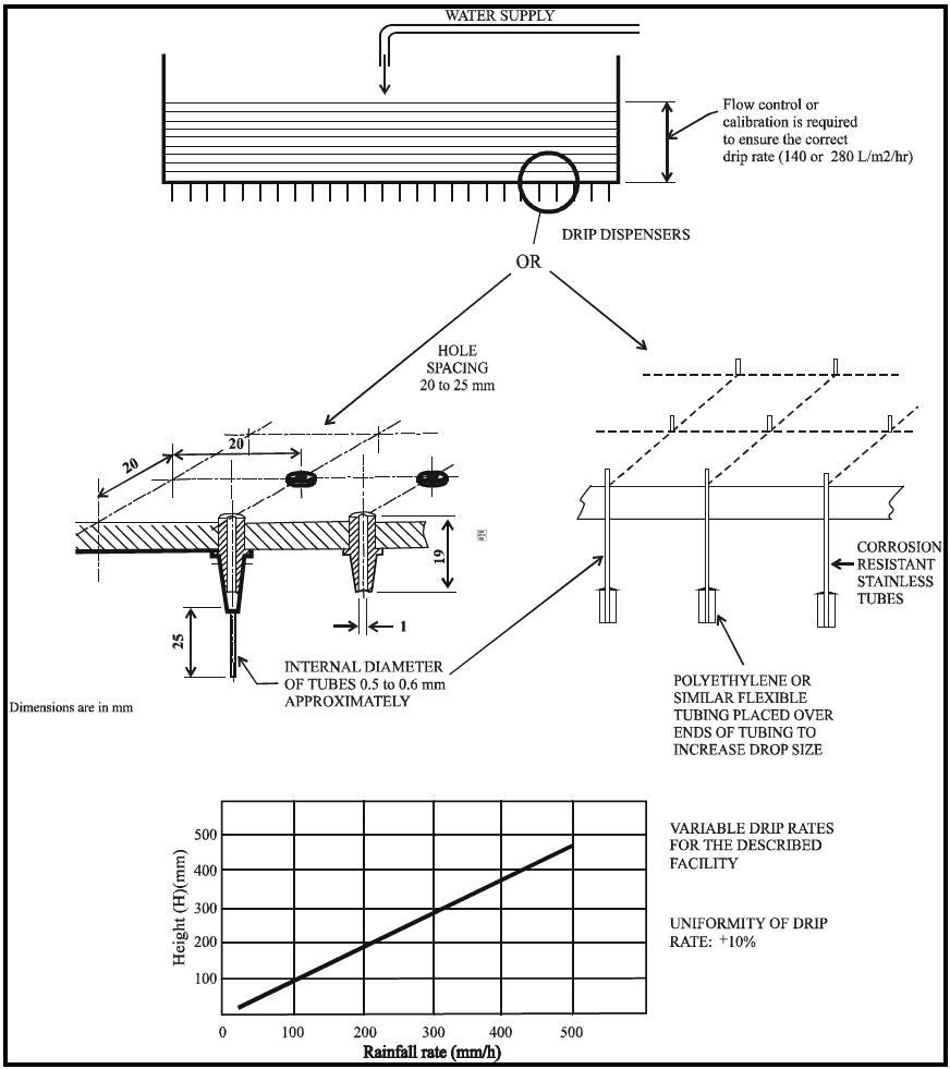
Figure description:
Drip Rainfall Simulation Facility Design and Calibration Chart UNIFORMITY OF DRIP RATE: +10%
VARIABLE DRIP RATES FOR THE DESCRIBED FACILITY
Annotations
- VARIABLE DRIP RATES FOR THE DESCRIBED FACILITY (text_label - position: Located to the right of the plot area)
- UNIFORMITY OF DRIP RATE: +10% (text_label - position: Located below the facility label on the right)
| Rainfall rate (mm/h) | Height (H (mm)) |
|---|---|
| 22 | 30 |
| 100 | 100 |
| 200 | 190 |
| 300 | 280 |
| 400 | 370 |
| 500 | 460 |
Notes: The figure details a facility for simulating rainfall with variable drip rates. Key features illustrated in the schematic include:
- A water supply tank with flow control or calibration required to maintain drip rates of 140 or 280 L/m²/hr.
- Two alternative drip dispenser designs:
- The first design (left detail uses a grid of holes with spacing between 20 and 25 mm. The dispensers are mounted in a 19 mm thick plate, extending 25 mm below it. The tubes have an internal diameter of approximately 0.5 to 0.6 mm and an external tip diameter of approximately 1 mm.
- The second design (right detail consists of corrosion-resistant stainless tubes with polyethylene or similar flexible tubing placed over the ends to increase drop size.
- All dimensions provided in the schematic are in millimeters (mm.
- The calibration chart shows a nearly linear relationship between the rainfall rate (mm/h and the required water height H (mm in the supply tank, following the approximate formula H = 0.9 * Rainfall rate + 10.
Figure 506.6-1. Sample facility for steady state rain or drip test.
4.1.2 Procedure II - Exaggerated
Use nozzles that produce a square spray pattern or other overlapping pattern (for maximum surface coverage) and with a droplet size predominantly in the 500 to 4500 µm range at approximately 276 kPa (40 psig). Use at least one nozzle for each 0.56 m² (6 ft²) of surface area and position each about 48 cm (19 in.) from the test surface. Adjust this distance as necessary to achieve overlap of the spray patterns. A water-soluble dye such as fluorescein added to the rainwater may aid in locating and analyzing any water leaks. For Procedure II, position the nozzles as required by the test plan or as depicted on Figure 506.6-2. Although Figure 506.6-2 shows an S-280 shelter, the nozzle configuration is typical for larger test items. In general, ensure the sides and top of the test item are subjected to overlapping water spray patterns.
|
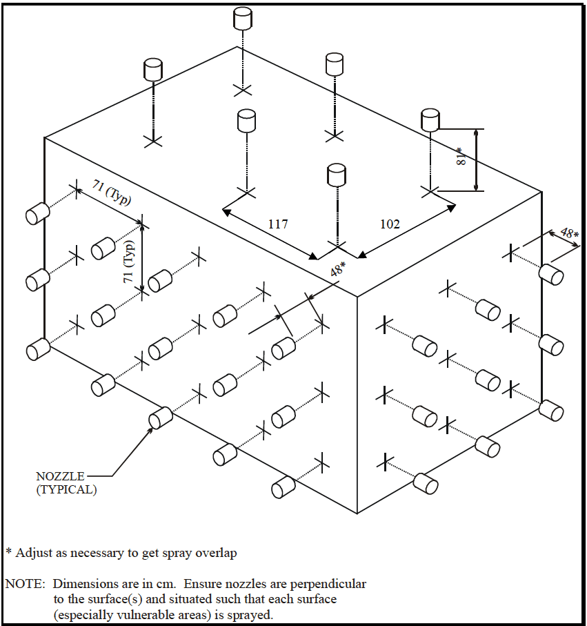
Figure description:
Key Information: Typical Nozzle Setup for Exaggerated Test (Procedure II
- Subject: Method 506.6 technical diagram illustrating nozzle positioning for spray testing on a rectangular object.
- Key Entities:
- Nozzles: Multiple spray units oriented perpendicular to the target surfaces.
- Test Object: A large rectangular enclosure.
- Dimensions (all in cm:
- Side Nozzle Spacing: 71 cm (Typical horizontal and vertical intervals.
- Top Nozzle Spacing: Intervals of 117 cm and 102 cm.
- Nozzle-to-Surface Distance: 48 cm for side nozzles and 81 cm for top nozzles.
- Notes:
- Distances marked with an asterisk (* are adjustable to ensure proper spray overlap.
- Nozzles must be perpendicular to the surface.
- Setup must ensure all surfaces, specifically vulnerable areas, receive spray coverage.
Figure 506.6-2. Typical nozzle setup for exaggerated test, Procedure II (not intended for use when conducting Procedure I testing).
4.1.3 Procedure III - Drip
Use a test setup that provides a volume of water greater than 280 l/m²/hr (7 gal/ft²/hr) dripping from a dispenser with drip holes on a 20 to 25.4 mm (0.79 – 1.0 inch) pattern (depending on which dispenser is used) but without coalescence of the drips into a stream. Figures 506.6-1 and 506.4-3 provide possible dispenser designs. Either arrangement shown on Figure 506.6-1 is recommended over that of Figure 506.6-3 due to its simplicity of construction, maintenance, cost, and reproducibility of tests. The polyethylene tubing is optional, but it ensures maximum droplet size. Use a drip height from a specified height (no less than 1 meter (3 feet)) as measured from the upper main surface of the test item Use a dispenser with a drip area large enough to cover the entire top surface of the test item. For known conditions where a 280 L/m²/hr (7 gal/ft²/hr) drip rate cannot occur, test the item by reducing the drip rate and increasing the test duration. For example, for an item exposed only to 140 L/m²/hr (3.5 gal/ft²/hr), appropriately reduce the drip rate as long as the duration of the test is extended to 30 minutes to ensure the equivalent volume of water falls on the test item. A water-soluble dye such as fluorescein added to the rainwater may aid in locating and analyzing water leaks. Recommend the water be filtered using a fine sediment filter to ensure particulate buildup does not block the tubing.
|
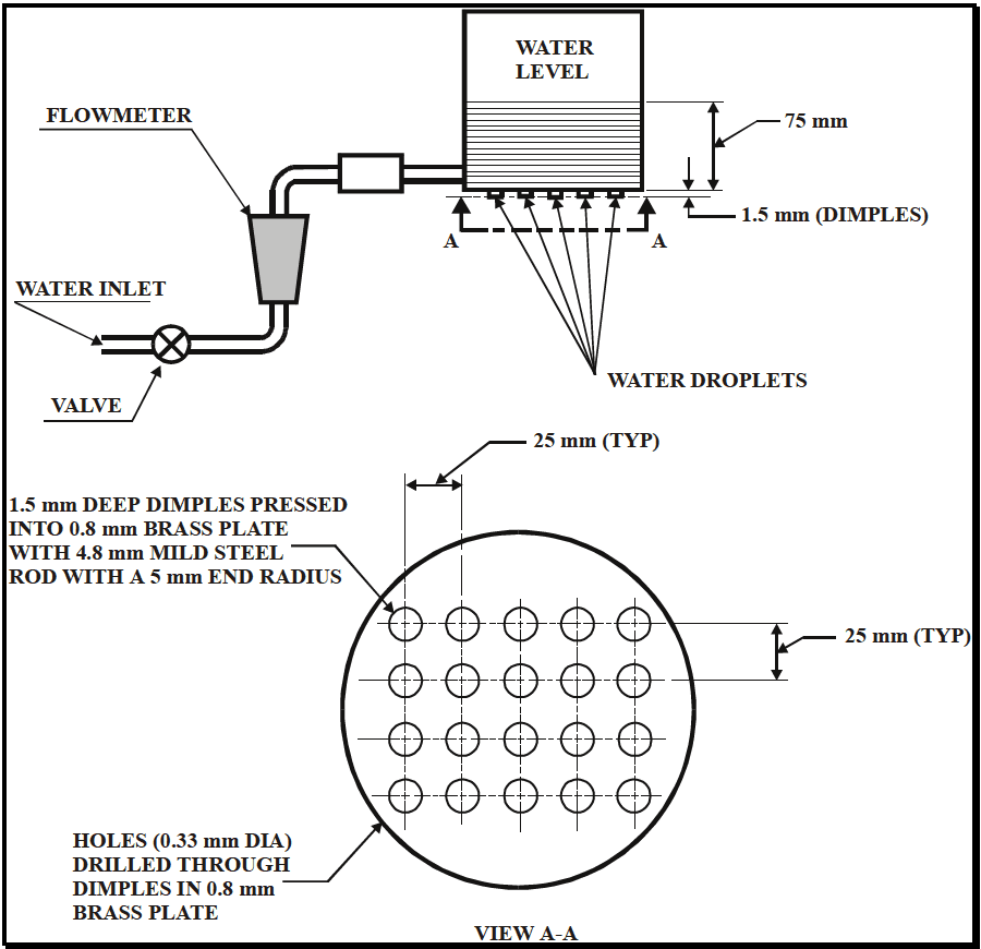
Figure description:
Figure 506.6-3: Details of Dispenser for Drip Test, Procedure III
Main Components:
- Water Supply: Inlet with valve and flowmeter leading to a reservoir.
- Water Reservoir: Maintains a water level of 75 mm.
- Dispensing Plate (View A-A: A 0.8 mm thick brass plate located at the bottom of the reservoir.
Technical Specifications:
- Dimples: 1.5 mm deep, pressed into the brass plate using a 4.8 mm mild steel rod with a 5 mm end radius.
- Holes: 0.33 mm diameter, drilled through the center of each dimple.
- Grid Spacing: Dimples/holes are arranged in a grid with 25 mm typical spacing both horizontally and vertically.
Figure 506.6-3. Details of dispenser for drip test, Procedure III.
4.2 Controls
- a. For Procedures I and II, verify the rainfall rate immediately before each test.
- b. For Procedure I, verify the wind velocity immediately before each test.
- c. For Procedures I and II, verify the nozzle spray pattern and pressure before each test.
- d. For Procedure III, verify the flow rate immediately before and after the test to ensure test tolerances are met throughout the test, and ensure that only separate (or discrete) drops are issuing from the dispensers.
- e. Unless otherwise specified, water used for rain tests can be from local water supply sources.
- f. Record test parameters at a sufficient rate to capture data necessary for post-test analysis (see Part One, paragraph 5.18).
MIL-STD-810H
METHOD 506.6
4.3 Test Interruption
Test interruptions can result from two or more situations, one being from failure or malfunction of test chambers or associated test laboratory equipment. The second type of test interruption results from failure or malfunction of the test item itself during required or optional performance checks.
4.3.1 Interruption Due to Chamber Malfunction
- a. General. See Part One, paragraph 5.11 of this Standard.
- b. Specific to this Method. Interruption of a rain test is unlikely to generate any adverse effects. Normally, continue the test from the point of interruption.
4.3.2 Interruption Due to Test Item Operation Failure
Failure of the test item(s) to function as required during mandatory or optional performance checks during testing presents a situation with several possible options.
- a. The preferable option is to replace the test item with a “new” one and restart from Step 1.
- b. A second option is to replace / repair the failed or non-functioning component or assembly with one that functions as intended, and restart the entire test from Step 1.
NOTE: When evaluating failure interruptions, consider prior testing on the same test item and consequences of such.
4.4 Test Execution
The following steps, alone or in combination, provide the basis for collecting necessary information concerning the materiel's watertightness.
4.4.1 Preparation for Test
4.4.1.1 Preliminary Steps
Before starting the test, review pretest information in the test plan to determine test details (e.g., procedures, test item configuration/orientation, cycles, durations, parameter levels for storage/operation, rainfall rates and wind velocities (for Procedure I), etc.). (See paragraph 3.1, above.)
4.4.1.2 Pretest Standard Ambient Checkout
All test items require a pretest standard ambient checkout to provide baseline data. Conduct the checkout as follows:
- Step 1. Stabilize the test item at standard ambient conditions (Part One, paragraph 5.1), in the test chamber whenever possible.
- Step 2. Conduct a complete pretest examination and document the results.
- Step 3. Prepare the test item in accordance with Part One, paragraph 5.8 and in the required test item configuration.
- Step 4. To establish baseline data, conduct an operational checkout in accordance with the test plan, and record the results. If required to support detection of water intrusion, weigh the test item.
- Step 5. If the test item operates satisfactorily, proceed to paragraph 4.4.2, 4.4.3, or 4.4.4 as appropriate. If not, resolve the problems and repeat Steps 3 and 4 above.
4.4.2 Procedure I - Rain and Blowing Rain
- Step 1. Heat the test item or cool the water so that the stabilized test item temperature is a minimum of 10 °C (18 °F) above the rain water temperature at the start of each exposure period (see paragraph 2.3.7).
Step 2. Install the test item in the facility in the configuration defined in the test plan.
MIL-STD-810H
METHOD 506.6
Step 3. Initiate the wind speed and rain rate specified in the test plan and maintain these conditions for a minimum of 30 minutes. If required, operate the test item for the last 10 minutes of the 30-minute rain exposure. If the test item fails to operate as intended, follow the guidance in paragraph 4.3.2 for test item failure.
Step 4. Examine the test item in the test chamber (if possible), otherwise, remove the test item from the test facility and conduct a visual inspection.
Step 5. Measure and document any free water found inside the protected areas of the test item. If required, weigh the test item.
Step 6. Repeat Steps 1 through 5 until all exposure surfaces of concern have been tested.
Step 7. Operate the test item for compliance with the requirements document, and document the results. See paragraph 5 for analysis of results. If water has penetrated the test item, judgment must be used before operation of the test item. It may be necessary to empty water from the test item (and measure the quantity) to prevent a safety hazard.
4.4.3 Procedure II - Exaggerated
Step 1. Install the test item (with all doors, louvers, etc., closed) in the test facility.
Step 2. Position the nozzles as required by the test plan or as indicated in Figure 506.6-2.
Step 3. Spray all exposed surfaces of the test item with water for not less than 40 minutes per face.
Step 4. After each 40-minute spray period, inspect the interior of the test item for evidence of free water. Estimate its volume and the probable point of entry and document. If required, weigh the test item.
Step 5. Conduct an operational check of the test item as specified in the test plan, and document the results. See paragraph 5 for analysis of results.
4.4.4 Procedure III - Drip
Step 1. Install the test item in the facility in accordance with Part One, paragraph 5.8 and in its operational configuration with all connectors and fittings engaged. Ensure the temperature differential between the test item and the water is 10 °C (18 °F) or greater. If necessary, either raise the test item temperature or lower the water temperature to achieve the differential in paragraph 2.3.7, and restore the test item to its normal operating configuration immediately before testing.
Step 2. Verify the proper water flow rate and ensure that only separate (or discrete) drops are issuing from the dispensers.
Step 3. With the test item operating, subject it to water falling from a specified height (no less than 1 meter (3 feet)) as measured from the upper main surface of the test item at a uniform rate for 15 minutes or as otherwise specified (see Figure 506.6-1 or Figure 506.6-3). Use a test setup that ensures that all of the upper surfaces get droplets on them at some time during the test. For test items with glass-covered instruments, tilt them at a 45° angle, dial up. If the test item fails to operate as intended, follow the guidance in paragraph 4.3.2 for test item failure.
- Step 4. At the conclusion of the 15-minute exposure, remove the test item from the test facility and remove sufficient panels or covers to allow the interior to be seen. Verify the proper water flow rate.
Step 5. Visually inspect the test item for evidence of water penetration.
Step 6. Measure and document any free water inside the test item. If required, weigh the test item.
- Step 7. Conduct an operational check of the test item as specified in the test plan, and document the results. See paragraph 5 for analysis of results.