Several terms need to be carefully defined for contrasting MET with SET. The term “test configuration” used in this document will refer to the totality of description for laboratory testing including the sources of excitation, test item fixturing, and orientation. In either testing configuration, distinction must be made between excitation measurement in a vector axis of excitation, and measurement on the test item in either the vector axis of excitation or in another vector different from the vector axis of excitation. Generally, to avoid confusion in specification and reporting, the vector directions of excitation and measurement must be specified in terms of a single laboratory inertial frame of reference related to the test configuration. In addition, it is helpful to specify the test item geometrical configuration along with the dynamic properties such as mass moments of inertia relative to the single laboratory inertial frame of reference.
- a. Single-Degree-of-Freedom (SDOF) – motion defined by materiel movement along or about a single axis whose description requires only one coordinate to completely define the position of the item at any instant.
- b. Multi-Degree-of-Freedom (MDOF) – motion defined by test item movement along or about more than one axis whose description requires two or more coordinates to completely define the position of the item at any instant.
- c. Single-Axis (SA) - excitation or response measurement in a unique single vector direction (linear or rotational). For rotational axis, the vector direction is perpendicular to the plane of rotation of the exciter or test item. Figure 527.2-1 displays a single-axis input in the vertical direction to an extended structure.
- d. Multi-Axis (MA) – excitation or response measurement that requires more than one unique vector for description. Refer to Figures 527.2-2 and 527.2-3 for MA examples of both two-axis and three-axis inputs to a common structure.
- e. Single-Exciter/Single-Axis (SESA) - application of a single exciter providing dynamic input to the test item in a single vector direction. All SET configurations are SESA by definition.
- f. Multi-Exciter/Single-Axis (MESA) – application of multiple exciters providing dynamic input to the test item in a single vector direction. For example, extended materiel might require excitation at the forward and aft end in a single vector axis as illustrated in Figure 527.2-2. If the definition of excitation requires more than a single vector, refer to the MEMA definition.
MIL-STD-810H
METHOD 527.2
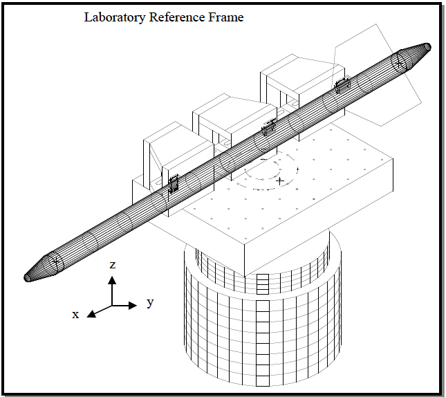
Figure description:
Key Information:
- Subject: Single exciter vertical axis (SESA test setup illustration.
- Test Specimen: A long, missile-shaped cylindrical object with fins, secured by three mounting fixtures.
- Equipment:
- Vertical Exciter: Large cylindrical base providing vertical motion.
- Test Platform: Rectangular top plate with a grid pattern and rotational indicators around a center point.
- Reference Frame: Cartesian coordinate system (x, y, z where the z-axis represents the vertical excitation direction.
- Context: Technical diagram for MIL-STD-810H, Method 527.2.
Figure 527.2-1. SESA - Single exciter vertical axis test setup.
Figure 527.2-2 illustrates a two-exciter application. Note that the system would require appropriate bearing assemblies to allow a pure rotational MESA or combined linear and rotational MEMA motion.
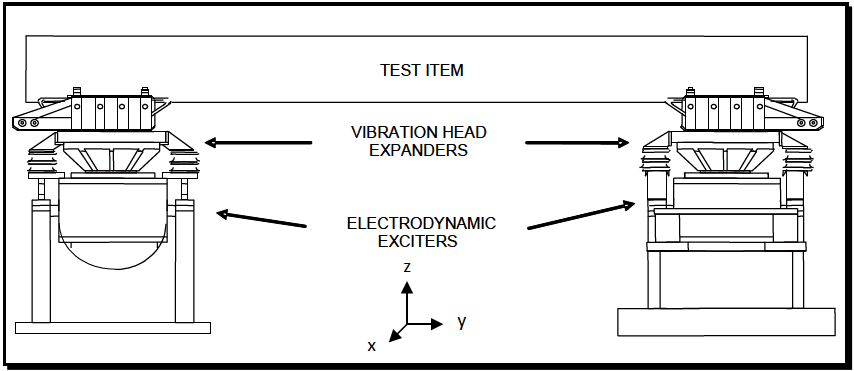
Figure description:
-
Key Entities:
- Test Item: Large rectangular component undergoing vibration testing.
- Vibration Head Expanders: Two units mounted between the exciters and the test item to distribute force.
- Electrodynamic Exciters: Two base units providing mechanical excitation to the assembly.
- Coordinate System: 3D axis showing vertical (Z, longitudinal (Y, and lateral (X directions.
-
System Configuration:
- Two-exciter setup designed for MESA (Multi-Exciter Single-Axis or MEMA (Multi-Exciter Multi-Axis motion.
- Exciters are positioned at opposite ends of the test item.
Figure 527.2-2. MESA (if control configured for two exciter 1-DOF motion) or MEMA (if control and mechanical couplings configured for two exciter 2-DOF motion).
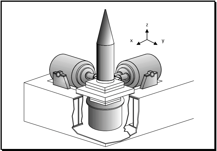
Figure description:
Key Entities and Information:
- System Type: MEMA Tri-axial exciter test setup for translational degrees-of-freedom.
- Test Specimen: A central, cone-tipped cylindrical payload mounted on a platform.
- Excitation Components:
- Three orthogonal shakers (exciters corresponding to the X, Y, and Z axes.
- Horizontal Exciters: Two units positioned at a 90-degree angle to provide lateral vibration (X and Y axes.
- Vertical Exciter: One unit positioned directly beneath the platform (Z-axis, shown via a cutaway in the base.
- Coordinate System: A legend indicates the three-dimensional translational axes (x, y, z.
Figure 527.2-3. MEMA - Tri-axial exciter test setup (Translational Degrees-of-Freedom).
- g. Multi-Exciter/Multi-Axis (MEMA) - Application of multiple exciters providing dynamic input to the test item in a way that requires more than a single vector for complete description of excitation and measurement. Figure 527.2-3 displays a three exciter three axis test. Three axes vertical, transverse, and longitudinal are required to describe the test. Note that many multi-axis test platform configurations have been built in recent years. Common 6 exciter examples are the hexapod (Stewart Platform), MAST, and Team Cube. There are also over-determined actuated systems consisting of more than 6 exciters. In each case, the dynamic properties vary between designs, and must be considered in the design of a MET.
- h. Single-Input/Single-Output (SISO) - refers to input of a single drive signal to an exciter system in an SDOF configuration and a single measured output from the fixture or test item in an SDOF configuration.
- i. Single-Input/Multiple-Output (SIMO) - refers to input of a single drive signal to an exciter system in a SDOF configuration, and multiple measured outputs from the fixture or test item in a MDOF configuration. In general, for specification purposes the dynamic behavior of the test item will not be assumed to contribute to the output DOF, i.e., measured rotation of an extended test item that is being excited in a cantilever mode will still basically be considered as a SET with linear acceleration characterizing the output.
- j. Multiple-Input/Single-Output (MISO) - refers to input of a multiple drive signals to an exciter system configuration in a MDOF configuration, and a single measured output from the fixture or test item in a SDOF configuration. This terminology is most used in measurement data processing where the single output is a composite of measurements from multiple inputs.
- k. Multiple-Input/Multiple-Output (MIMO) - refers to input of multiple drive signals to an exciter system configuration in a MDOF configuration, and multiple measured outputs from the fixture or test item in a MDOF configuration. It is important to note that generally there is no one-to-one correspondence between inputs and outputs, and the number of inputs and number of outputs may be different.
In the paragraphs to follow, generally only the terms MESA and MEMA will be used, however, for processing measurement data the terms SISO, SIMO, MISO, and MIMO are standard (paragraph 6.1, references a and c).
MIL-STD-810H
METHOD 527.2