4.1 Test Facility
Use a facility that can provide the required combination of three or more environmental elements. Verify that the facility is capable of meeting all test parameters; to include specified temperature and altitude ramp rates. See the guidance for the facilities for the individual element tests, i.e., latest revision of Methods 500, 501, 502, 507, and 514. Ensure the facility satisfies the requirements of Part One, paragraph 5.
4.1.1 Power Supplies
Use power supplies which have sufficient power capacity to account for start-up and operational current surges. At minimum, the power supply should be able to replicate the voltage and frequency characteristic of the platform (s) for Alternating Current sources or the voltage for Direct Current sources. The electrical characteristics are defined at the input terminals. It is highly recommended that the input electrical power characteristics be measured at the input terminals of the equipment under test (see MIL-HDBK-704, section 4, general information). If power characteristics, such as transients or interrupts, are required, use programmable power supplies as necessary.
4.2 Controls / Tolerances
Ensure calibration procedures are consistent with the guidance provided in Part One 5.3.2. Ensure test tolerance procedures are consistent with the guidance provided in Method 514 Paragraph 4.2.2
4.3 Test Interruption
Test interruptions can result from two or more situations, one being from failure or malfunction of test chambers or associated test laboratory equipment. The second type of test interruption results from failure or malfunction of the test item itself during functional tests.
4.3.1 Interruption Due To Facility Malfunction
- a. General. See Part One, paragraph 5.11 of this Standard.
- b. Specific to this Method.
- (1) Undertest interruption. Refer to the interruption guidance for the individual test elements, i.e., temperature, altitude, humidity, input electrical power, and vibration.
- (2) Overtest interruption. Refer to the interruption guidance for the individual test elements, i.e., temperature, altitude, humidity, input electrical power, and vibration.
- (3) In the case of failure of the Data Acquisition (DAQ) system (while the facilities are still working properly), take into account possible safety issues, if anything important may have been missed in the output/response of the materiel, and how much of the time DAQ was down. The test may be continued without any changes if there are no concerns, or may have temporary interruption just to get DAQ working again. If there are any concerns take the appropriate action based on the test interruption information in this Method as well as in Part One, paragraph 5.11 of this Standard.
4.3.2 Interruption Due To Test Item Operation Failure
Failure of the test item(s) to function as required during functional tests presents a situation with several possible options. Prior to restarting the test the root cause of the failure shall be determined, along with the remedial action. This determination will aid in determining which of the following options is preferred. The failure analysis shall be included in the test report. (See section 5 for additional guidance.)
- a. The preferable option is to replace the test item with a “new” one and restart from Step 1.
- b. A second option is to replace/repair the failed or non-functioning component or assembly with one that functions as intended, and restart the entire test from Step 1.
MIL-STD-810H
METHOD 520.5
- c. For non-relevant anomalies, which do not affect the functionality of the unit under test, following a review of the data, the test may be resumed at the start of the cycle.
NOTE: Test item failures may be the result of cumulative environmental stresses, including stresses from prior tests on the test item. When evaluating failure interruptions, evaluate prior testing on the same test item and consequences of such. This may necessitate the repetition of prior tests to validate the corrective action.
4.3.3 Scheduled Interruptions
There are situations in which scheduled test interruptions will take place. These interruptions shall be approved by the cognizant organization and documented in the test plan and/or the test report. Interruptions shall be scheduled so as to have the least impact on the test conditions. Preferably these interruptions shall occur during steady state environmental conditions or at the end of a cycle. Following the interruption, all test parameters, for both the test chamber and test item, shall be stabilized at the values immediately preceding the interruption. See also Part One paragraph 5.11.4. Scheduled interruptions may result from the following:
- a. Test Item Life Cycle Event: This would include the replacement of batteries or consumables, required reorientation of the test item during the test, etc. It also includes material operation which cannot be performed remotely. (Note: when possible, material operation shall be performed remotely via pneumatic/electrical actuators or by other means which do not compromise the test environment.
- b. Test Chamber/Support Equipment Events: These may include scheduled maintenance such as the periodic calibration of sensors, reconfiguration for alternate modes of operation, re-torqueing of fixtures, etc. Foreseen inclement weather may necessitate a test suspension and/or controlled shutdown due to the potential for power interruption and/or personnel limitations.
- c. Personnel events: It is preferred that testing be performed on a 24/7 work schedule. When this is not feasible, then the test shall be interrupted at the end of the cycle. The test chamber shall be maintained at standard ambient conditions during the interruption. Interruption of the test at other points of the test profile shall require approval from the cognizant organization.
4.4 Test Execution
The following steps, alone or in combination, provide the basis for collecting necessary information concerning the test item in a combined environment of temperature, altitude, humidity, input electrical power, and vibration. Begin with the first procedure specified in the test plan.
4.4.1 Preparation For Test
4.4.1.1 Preliminary Steps
Before starting the test, review pretest information in the currently approved test plan to determine test details (e.g., procedures, item configuration, cycles, durations, parameter levels for storage/operation, etc.). (See paragraph 3.1, above.)
4.4.1.2 Pretest Standard Ambient Checkout
All test items require a pretest standard ambient checkout to provide baseline data. Conduct the checkout as follows:
- Step 1: Conduct a visual examination of the test item with special attention to stress areas, such as corners of molded cases, and document the results.
- Step 2: Install the materiel in the test chamber in its operational configuration. Verify all electrical and mechanical connections.
- Step 3: In order to determine thermal response install temperature sensors in or on the test item as described in the test plan.
Step 4: Install any additional sensors and ancillary equipment as required by the test plan.
Step 5: Conduct a test of the data acquisition system and verify all data is being recorded.
MIL-STD-810H
METHOD 520.5
Step 6: Conduct a functional test (Part One, paragraph 5.8.2) at standard ambient conditions (Part One, paragraph 5.1) as described in the plan and record the results.
Step 7: If the test item operates satisfactorily, proceed to paragraph 4.4.2, 4.4.3, or 4.4.4 as appropriate. If not, resolve the problems and repeat Step 5 thru 6 above. If resolution requires replacement of the item, or removal, of sensors in order to repair, then repeat Steps 1 through 6 above.
4.4.2 Procedure I – Engineering Development
Procedure I may be used during engineering development to establish design margins and verify that the design meets its engineering requirements during exposure to the specified environments. Test profile development shall follow the guidance shown in table 520.5-VIII. Test parameters should be chosen based on the intent of the engineering test. Although based on the design specification, more extreme parameters may be preferred to establish design margins. Refer to Procedure III for an example of a platform envelope. For specific engineering tests, based on suspected failure modes, a specific segment of the profile may be conducted that incorporates test parameters more extreme than the specification requirement.
4.4.3 Procedure II – Flight or Mission Support
The Procedure II test profile is intended to simulate the climatic, dynamic, input electrical power, and operational events experienced in specific missions or troubleshooting scenarios. These missions represent specific geophysical areas of operation and do not cover the full platform envelope. No one profile is appropriate for use, rather separate profiles must be developed to cover the specific mission/troubleshooting scenario. The following paragraphs discuss representative mission segments. These segments may be combined, along with the appropriate transition parameters, to develop the mission profile. Some segments, such as cruise and attack, may be repeated at different portions of the profile and at different levels. All segments may, or may not, be required for specific missions/troubleshooting. These segments are not all encompassing and additional segments may be required.
Measured data is essential for each of these parameters to actually replicate the exact conditions for this segment. Test parameters are to be based on measured data to the greatest extent possible. These include the geophysical climatic data, specific environmental conditions of the equipment installation, dynamic response of the platform, and input power quality. When measured data is not available, MIL-HDBK-310 may be referenced for atmospheric data.
For each segment the forcing functions described below shall be evaluated in developing the profile. The maintenance and non-op segments may represent platform non-operational periods; or may represent materiel which is not installed on the platform and is either in the logistics supply chain (storage) or undergoing maintenance in a repair facility. The duration for each segment shall be determined by the mission scenario. This list is not all inclusive; additional forcing functions may be required for specific missions. The following mission segments are generally ordered for a representative mission. This order may vary depending on the specific mission.
4.4.3.1 Non-Operational/ Ground Soak
Measured data is essential for each of these parameters to actually replicate the exact conditions for this segment.
- a. Temperature: Determine the deployment location and any induced temperatures based on the materiel installation (solar loading, heating from adjacent material, etc.) (Stabilize to the mission ground soak temperature; day or night mission.) See Section 2.2.4.1 (Thermal Stress).
- b. Altitude: Site altitude of the deployment location. See Section 2.2.4.2 (Altitude Stress)
- c. Humidity: Measured humidity at the deployment location. See Section 2.2.4.3 (Humidity Stress).
4.4.3.2 Start Up/Taxi
-
a. Temperature: Ground soak temperature based on equipment location. (Note: Some materiel may receive conditioned air prior to start up.) Use measured data or thermal survey data. See Section 2.2.4.1 (Thermal Stress) and Section 2.2.4.1.1 (Bay Conditions).
-
b. Altitude: Site altitude of the deployment location. See Section 2.2.4.2 (Altitude Stress)
-
c. Humidity: Measured humidity at the deployment location. See Section 2.2.4.3 (Humidity Stress).
-
d. Input Electrical Power: Use measured data or data from the electrical loads analysis, including power transfer interrupts during transfer from ground to aircraft power. (If trouble shooting, consider the effects of power transients. Attempt to replicate aircraft power.) See Section 2.2.4.4 (Electrical Stress).
-
e. Supplemental Cooling: If required, the supplemental cooling shall meet the temperature and mass flow rates for the specific platform ECS system. For ECS systems open to the external environment, the mass flow rate to the LRU shall be adjusted for the pressure altitude. See Section 2.2.4.1 (Thermal Stress). It is imperative that the cooling system design be understood in order to properly replicate during test!
-
f. Vibration: Vibration levels shall be based on the functional vibration levels for the specific materiel location and the specific mission segment under test. Vibration levels may vary throughout the test. See section 2.2.4.5 (Vibration Stress) and Method 514, annex A, paragraph 2.1.2.1 (Functional Vibration Definition).
4.4.3.3 Climb to Cruise/Surveillance
- a. Temperature: Ramp the temperature from the ground/site temperature to the High Altitude/Cruise Temperature for the specific geophysical location. For external materiel use measured data or the appropriate atmospheric lapse rate (dry/humid) for the mission geophysical location. For internal materiel use measured data or thermal analysis/survey data Section 2.2.4.1.1 (Bay Conditions). For materiel designed for specific geophysical locations, if measured data is not available use data from MIL-HDBK-310. See Section 2.2.4.1 (Thermal Stress). The ramp rate shall be IAW the platform performance.
- b. Altitude: Ramp the altitude from the ground/site altitude to the High Cruise altitude. For pressurized compartments perform the ramp to the specified pressure altitude. The ramp rate shall be IAW the platform performance. See Section 2.2.4.2 (Altitude Stress).
- c. Humidity: Humidity shall be based on anticipated mission cruise altitude. (Note: For low level missions the humidity will essentially be the same as ground level.) See Section 2.2.4.3 (Humidity Stress).
- d. Input Electrical Power: Use measured data or data from the electrical loads analysis for Climb. (If trouble shooting, consider the effects of power transients. Attempt to replicate aircraft power.) See Section 2.2.4.4 (Electrical Stress).
- e. Supplemental Cooling: If required, the supplemental cooling shall meet the temperature and mass flow rates for the specific platform ECS system. For ECS systems open to the external environment, the mass flow rate to the LRU shall be adjusted for the pressure altitude. See Section 2.2.4.1 (Thermal Stress). It is imperative that the cooling system design be understood in order to properly replicate during test!
- f. Vibration: Vibration levels shall be based on the functional vibration levels for the specific materiel location and the specific mission segment under test. Vibration levels may vary throughout the test. See section 2.2.4.5 (Vibration Stress) and Method 514, annex A, paragraph 2.1.2.1 (Functional Vibration Definition).
4.4.3.4 Cruise/Surveillance
- a. Temperature: Maintain the cruise/surveillance temperature until the materiel has stabilized or for the duration of the platform cruise/surveillance mission. For long duration surveillance missions, such as UAS missions, a soak of 4 hours following stabilization is generally sufficient. This data may be available from the program office. See Section 2.2.4.1 (Thermal Stress).
- b. Altitude: Maintain the cruise/surveillance altitude until the materiel has thermally stabilized or for the duration of the platform cruise mission. This data may be available from the program office. See Section 2.2.4.2 (Altitude Stress).
- c. Humidity: For low level cruise, the humidity will track the ground level measured humidity for the geophysical location. For high level cruise the humidity will be uncontrolled. See Section 2.2.4.3 (Humidity Stress).
- d. Input Electrical Power: Use measured data or data from the electrical loads analysis for cruise. (If trouble shooting, consider the effects of power transients. Attempt to replicate aircraft power.) See Section 2.2.4.4 (Electrical Stress).
- e. Supplemental Cooling: If required, the supplemental cooling shall meet the temperature and mass flow rates for the specific platform ECS system. For ECS systems open to the external environment, the mass flow rate
to the LRU shall be adjusted for the pressure altitude. See Section 2.2.4.1 (Thermal Stress). It is imperative that the cooling system design be understood in order to properly replicate during test!
- f. Vibration: Vibration levels shall be based on the functional vibration levels for the specific materiel location and the specific mission segment under test. Vibration levels may vary throughout the test. See section 2.2.4.5 (Vibration Stress) and Method 514, annex A, paragraph 2.1.2.1 (Functional Vibration Definition).
4.4.3.5 Attack
- a. Temperature: The temperature levels in this segment will vary depending on the type of attack mission: low level ground attack, high altitude air to air, etc. External equipment may experience rapid temperature changes as the platform traverses different thermal layers of the atmosphere. Internal equipment temperatures are expected to remain relatively constant. See Section 2.2.4.1 (Thermal Stress).
- b. Altitude: The altitude may vary rapidly, up to the maximum platform specification rate. During a mission, multiple attack scenarios/events may occur. See Section 2.2.4.2 (Altitude Stress).
- c. Humidity: For low level attack, the humidity will track the ground level measured humidity for the geophysical location. For high level attack the humidity will be uncontrolled. See Section 2.2.4.3 (Humidity Stress).
- d. Input Electrical Power: Use measured data or data from the electrical loads analysis for attack. (If trouble shooting, consider the effects of power transients. Attempt to replicate aircraft power.) See Section 2.2.4.4 (Electrical Stress).
- e. Supplemental Cooling: If required, the supplemental cooling shall meet the temperature and mass flow rates for the specific platform ECS system. For ECS systems open to the external environment, the mass flow rate to the LRU shall be adjusted for the pressure altitude. See Section 2.2.4.1 (Thermal Stress). It is imperative that the cooling system design be understood in order to properly replicate during test!
- f. Vibration: Vibration levels shall be based on the functional vibration levels for the specific materiel location and the specific mission segment under test. Vibration levels may vary throughout the test. See section 2.2.4.5 (Vibration Stress) and Method 514, annex A, paragraph 2.1.2.1 (Functional Vibration Definition).
4.4.3.6 Descent/Landing
- a. Temperature: Ramp the temperature from the high altitude cruise temperature to the site temperature for the specific geophysical location. See Section 2.2.4.1 (Thermal Stress). The ramp rate shall be IAW the platform performance.
- b. Altitude: Ramp the altitude from the high altitude cruise/surveillance to the site altitude. The ramp rate shall be IAW the platform performance. See Section 2.2.4.2 (Altitude Stress).
- c. Humidity: Ramp the humidity to the measured value for the deployment site. If measured data is not available see MIL-HDBK-310. If descending into a warm/moist environment, there is the possibility that condensation will form on the materiel.
- d. Input Electrical Power: Use measured data or data from the electrical loads analysis for descent. (If trouble shooting, consider the effects of power transients. Attempt to replicate aircraft power.) See Section 2.2.4.4 (Electrical Stress).
- e. Supplemental Cooling: If required, the supplemental cooling shall meet the temperature and mass flow rates for the specific platform ECS system. For ECS systems open to the external environment, the mass flow rate to the LRU shall be adjusted for the pressure altitude. See Section 2.2.4.1 (Thermal Stress). It is imperative that the cooling system design be understood in order to properly replicate during test!
- f. Vibration: Vibration levels shall be based on the functional vibration levels for the specific materiel location and the specific mission segment under test. Vibration levels may vary throughout the test. See section 2.2.4.5 (Vibration Stress) and Method 514, annex A, paragraph 2.1.2.1 (Functional Vibration Definition).
MIL-STD-810H METHOD 520.5
4.4.3.7 Maintenance
- a. Temperature: Determine for the deployment location and any induced temperatures based on the material installation (solar loading, heating from adjacent material, etc.) Additional heat may be generated through the maintenance process of replacing specific components. See Section 2.2.4.1 (Thermal Stress).
- b. Altitude: Site altitude of the deployment location. See Section 2.2.4.2 (Altitude Stress)
- c. Humidity: Measured humidity at the deployment location. See Section 2.2.4.3 (Humidity Stress).
- d. Input Electrical Power (Ground Power/Aircraft Power); repeated power cycles may occur during maintenance. Ground Power shall replicate aircraft power and be within the aircraft normal operating limits. If troubleshooting, a power survey may be required of the specific aircraft power system to characterize the power quality at the LRU input. See Section 2.2.4.4 (Electrical Stress).
- e. Temperature Conditioned Air: When temperature conditioned air (heating/cooling) is required for maintenance in the field, conditioned air shall be provided to simulate the field maintenance conditions. (Note: Conditioned Air may not be available for all deployment locations/maintenance conditions. Test conditions should represent the actual conditions found in the field when possible.)
MIL-STD-810H
METHOD 520.5
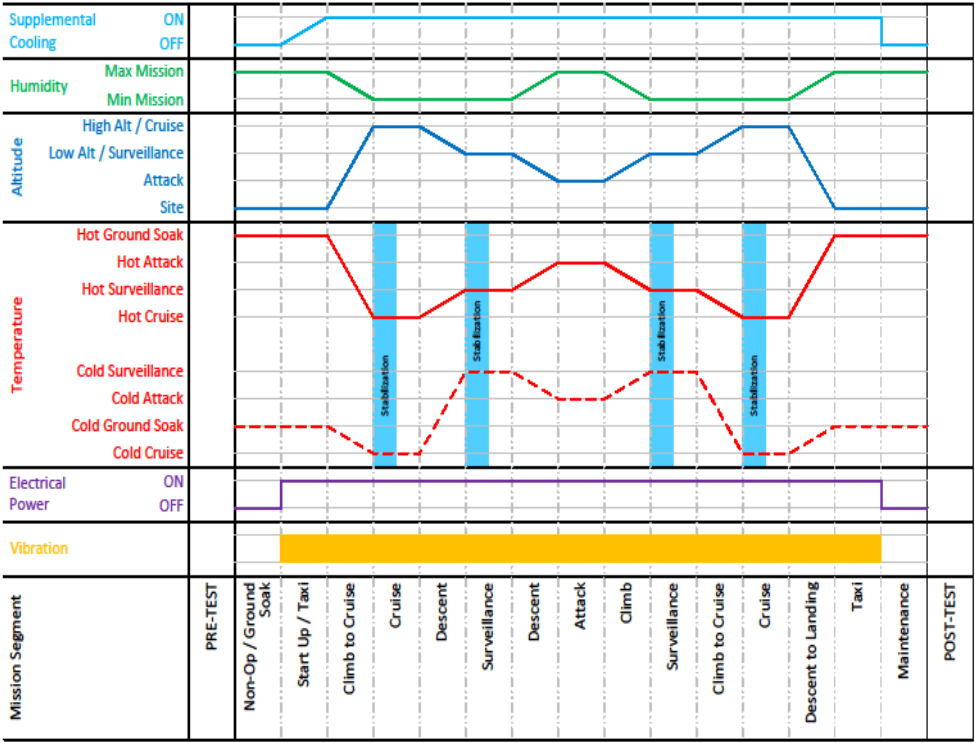
Figure description:
Mission Segment Chart Parameter Profiles by Mission Segment
Mission Test Profile
Legend
- Supplemental Cooling — color: light blue; symbol: Solid line
- Humidity — color: green; symbol: Solid line
- Altitude — color: blue; symbol: Solid line
- Hot Temperature — color: red; symbol: Solid line
- Cold Temperature — color: red; symbol: Dashed line
- Electrical Power — color: purple; symbol: Solid line
- Vibration — color: yellow; symbol: Filled block
Annotations
- Stabilization (shaded_area - position: x = early Cruise (first instance))
- Stabilization (shaded_area - position: x = mid Surveillance (first instance))
- Stabilization (shaded_area - position: x = mid Surveillance (second instance))
- Stabilization (shaded_area - position: x = early Cruise (second instance))
| Mission Segment | Supplemental Cooling | Humidity | Altitude | Hot Temperature (Solid Line) | Cold Temperature (Dashed Line) | Electrical Power | Vibration |
|---|---|---|---|---|---|---|---|
| PRE-TEST | OFF | Max Mission | Site | Hot Ground Soak | Cold Ground Soak | OFF | OFF |
| Non-Op / Ground Soak | OFF | Max Mission | Site | Hot Ground Soak | Cold Ground Soak | OFF | OFF |
| Start Up / Taxi | OFF to ON | Max Mission | Site | Hot Ground Soak | Cold Ground Soak | ON | ON |
| Climb to Cruise | ON | Max Mission to Min Mission | Site to High Alt / Cruise | Hot Ground Soak to Hot Cruise | Cold Ground Soak to Cold Cruise | ON | ON |
| Cruise | ON | Min Mission | High Alt / Cruise | Hot Cruise | Cold Cruise | ON | ON |
| Descent | ON | Min Mission to Max Mission | High Alt / Cruise to Low Alt / Surveillance | Hot Cruise to Hot Surveillance | Cold Cruise to Cold Surveillance | ON | ON |
| Surveillance | ON | Max Mission | Low Alt / Surveillance | Hot Surveillance | Cold Surveillance | ON | ON |
| Descent | ON | Max Mission to Min Mission | Low Alt / Surveillance to Attack | Hot Surveillance to Hot Attack | Cold Surveillance to Cold Attack | ON | ON |
| Attack | ON | Min Mission | Attack | Hot Attack | Cold Attack | ON | ON |
| Climb | ON | Min Mission to Max Mission | Attack to Low Alt / Surveillance | Hot Attack to Hot Surveillance | Cold Attack to Cold Surveillance | ON | ON |
| Surveillance | ON | Max Mission | Low Alt / Surveillance | Hot Surveillance | Cold Surveillance | ON | ON |
| Climb to Cruise | ON | Max Mission to Min Mission | Low Alt / Surveillance to High Alt / Cruise | Hot Surveillance to Hot Cruise | Cold Surveillance to Cold Cruise | ON | ON |
| Cruise | ON | Min Mission | High Alt / Cruise | Hot Cruise | Cold Cruise | ON | ON |
| Descent to Landing | ON | Min Mission to Max Mission | High Alt / Cruise to Site | Hot Cruise to Hot Ground Soak | Cold Cruise to Cold Ground Soak | ON | ON |
| Taxi | ON | Max Mission | Site | Hot Ground Soak | Cold Ground Soak | ON | ON |
| Maintenance | OFF | Max Mission | Site | Hot Ground Soak | Cold Ground Soak | OFF | OFF |
| POST-TEST | OFF | Max Mission | Site | Hot Ground Soak | Cold Ground Soak | OFF | OFF |
Notes: The chart illustrates a synchronized test profile for multiple environmental and electrical parameters across 17 mission segments. Temperature levels are categorized by specific operational states (Ground Soak, Attack, Surveillance, Cruise for both hot and cold scenarios. 'Stabilization' periods are highlighted during long-duration flight phases.)
Figure 520.5-2. Mission Specific/Troubleshooting Test Profile (Hot and Cold Day/Ground Attack) Notional Example (See notes for additional information.) Figure 520.5-2. Notes:
- Procedure II is intended for testing of unique mission profiles and troubleshooting. The profile steps must be tailored for the specific application. Steps may be added, repeated, or deleted based on the specific mission requirements.
- Temperatures and Altitudes for troubleshooting shall be obtained from actual mission data, if possible.
- Temperatures and Altitudes for mission specific testing shall be obtained from the relevant program office or mission needs statement based on the mission geophysical location.
- Temperature Ramp Rate: IAW equipment or platform specification. If not specified, then <5 Deg C/min.
- Altitude Ramp Rate: IAW Equipment for platform specification.
- Humidity: The specific relationship between temperature, altitude, and humidity is highly variable and the profile should be considered as an example only. This parameter should be analyzed based on the specific mission geographic and atmospheric conditions. (Note: in the attack segment, if test chamber is unable to apply humidity at altitude, then this segment may be set to site pressure to incorporate the humidity parameter. This simulates a low level attack in a humid environment.)
- Input Electrical Power:
-
a. Voltage: Alternate from cycle to cycle; Nominal, High, Low, High, etc. See Tables 520.5-III, IV, V, and VI for guidance.
-
b. Frequency Variation: The input electrical power frequency shall be varied from cycle to cycle. See Tables 520.5-III, V, and VI for guidance.
Note: Flight critical equipment may be required to operate under abnormal and/or emergency voltage condition. See Table IV and MIL- STD-704 for the appropriate levels. See paragraph 2 2.4.4. for additional guidance.
- Supplemental Cooling temperature and mass flow rate shall be IAW the platform/system specification. There shall be no ECS supplemental cooling for the first 2 minutes following power on. This shall be followed by a linear drop in the ECS supplemental cooling air temperature to the specified cooling temperature. The ECS cooling air temperature ramp rate shall be determined from the platform ECS specification. For RAM cooled compartment a thermal analysis shall be performed per the guidance in paragraph 2.2.4.1.1.a.
- Vibration may be performed separately with temperature. Vibration is intended to be tailored for the test items specific rotorcraft and/or fixed wing application and the levels should be in accordance with the levels expected during the specific mission segments.
- It is preferred that consecutive cycles be run continuously; however, if test chamber operations preclude continuous operation, then the transition from high altitude to site, and from loiter temperature to minimum temperature shall be completed prior to interrupting the cycles. These conditions shall be maintained until the cycle is resumed.
- Pre-Test, Post-test and Functional tests are performed to verify consistent satisfactory performance throughout the test. Pre and Post tests are generally the same. Functional tests, especially during altitude exposure, may be dependent on chamber access. These tests should be tailored per guidance in Part One.
4.4.4 Procedure III – Platform Envelope
Procedure III is intended to verify operation across the platform envelope during exposure to multiple forcing functions. The test parameters are derived from the platform/materiel specification and tailored for the specific equipment location(s). There are two options within the procedure.
Option 1 applies materiel which, during its life cycle, is expected to be powered “ON” at temperatures either less than or greater than the normal operational temperature(s). This includes materiel that is powered “ON” concurrent with aircraft startup or that is powered “ON” while the aircraft is on the tarmac in a thermally ground soaked condition. Unless otherwise specified, the minimum and maximum start up temperatures will generally equate to the minimum and maximum ground soak temperatures (Figure 520.5-3a).
Option 2 applies to materiel which is powered “ON” during flight operations after the aircraft temperature has stabilized at its normal operational temperature. (Figure 520.5-3b)
Table 520.5-IX, Template: Procedure III Envelope test cycle (Based on Option 1) may be used to assist in development of the test profile. During testing, the completed table may also provide a quick reference to the test conditions at specific points in the test profile.
MIL-STD-810H
METHOD 520.5
Table 520.5-IX Template: Procedure I and III - Envelope test cycle (Based on Option 1)
The following table correlates to the profile steps and typical mission segments. This template shall be populated with actual parameters derived from Table 520.5-VIII. Reference Paragraph 2.3.1, Table 520.5-VIII, Step 9
| STEP | Test Phase Definition | Temp °C (°F) | Relative Humidity | Supp. Cooling Air °C (°F) | Supp. Cooling Mass Flow (lbs/min) | Altitude | Test Item- Operating/non op. | Func Test | Duration |
|---|---|---|---|---|---|---|---|---|---|
| 1 | Pre-Test Set-up and Functional Test at Standard Ambient | Standard Ambient | Uncontrolled | N/A | N/A | Site | Operating/Non- operating (Note 8) | Yes | As Required |
| 2.a | Ramp to Cold/Dry Min Power ON Temp | Ramp (Notes 1,2) | Uncontrolled | N/A | N/A | Site | Non-Operating | No | As Required |
| 2.b | Cold/Dry Stabilization | Min. Power ON Temp (Notes 1, 3) | Uncontrolled | N/A | N/A | Site | Non-operating | No | As Required (See Part One, paragraph 5.4) |
| 2.c | Cold/Dry Warm-up | Min. Power ON Temp (Note: Conditioned Air may be required for some equipment.) | Uncontrolled | N/A | N/A | Site | Operating (Note 8) | No | Minimum time required to perform power up and specified warm-up |
| 2.d | Cold/Dry Functional test | Min. Power ON Temp (Note: Conditioned Air may be required for some equipment.) | Uncontrolled | N/A | N/A | Site | Operating (Note 8) | Yes | Minimum time required to perform functional test |
| 2.e | Ramp to Op Temp (Warm-up) | Ramp (Notes 1, 2) | Uncontrolled | N/A | N/A | Site | Operating | No | As required |
| 3 | Cold/Dry Soak | Min. Op Temp (Note 1) | Uncontrolled | N/A | N/A | Site | Operating | No | 2 hours minimum |
| 4 | Cold/Dry Functional test | Min. Op Temp (Note 1) | Uncontrolled | N/A | N/A | Site | Operating | Yes | Minimum time required to perform functional test |
MIL-STD-810H
METHOD 520.5
Table 520.5-IX (Con't) Template: Procedure I and III - Envelope test cycle (Based on Option 1)
The following table correlates to the profile steps and typical mission segments. This template shall be populated with actual parameters derived from Table 520.5-VIII. Reference Paragraph 2.3.1, Table 520.5-VIII, Step 9
| STEP | Test Phase Definition | Temp °C (°F) | Relative Humidity | Supp. Cooling Air °C (°F) | Supp. Cooling Mass Flow (lbs/min) | Altitude | Test Item- Operating/non op. | Func Test | Duration |
|---|---|---|---|---|---|---|---|---|---|
| 5 | Ramp to Warm/Moist | Ramp to 32°C (Note 2) | Ramp to > 95% RH (Note 10) | N/A | N/A | Site | Non-operating | No | As Required |
| 6 | Warm/Moist Soak | 32°C (90°F) | 95% RH | N/A | N/A | Site | Non-operating | No | 1 hour minimum |
| 7 | Warm/Moist Functional Test | 32°C (90°F) | 95% RH | N/A | N/A | Site | Operating | Yes | As Required |
| 8 | Ramp to Cold/Dry Altitude | Ramp to Min Op Temp (Notes 1,2) | Uncontrolled | N/A | N/A | Ramp to Max Op Alt (Notes 4, 5) | Operating | No | As Required |
| 9 | Cold/Dry Altitude Soak | Min Op Temp | Uncontrolled | N/A | N/A | Max Op Alt | Operating | No | Stabilization, plus one hour; or 2 hours, whichever is less |
| 10 | Cold/Dry Altitude Functional test | Min Op Temp | Uncontrolled | N/A | N/A | Max Op Alt | Operating | Yes | |
| 11 | Ramp to Warm/Moist | Ramp to site (Note 2) | Ramp to ≥ 95% RH (Note 10) | N/A | N/A | Ramp (Note 5) | Operating | No | As Required |
| 12 | Warm/Moist Soak | +35°C | ≥ 95% RH | N/A | N/A | Site | Operating | No | 30 minutes minimum |
| 13 | Warm/Moist Functional test | +35°C | > 95% RH | N/A | N/A | Site | Operating | Yes | As Required |
| 14 | Power Off | +35°C | ≥ 95% RH | N/A | N/A | Site | Non-Operating | No | As Required |
MIL-STD-810H
METHOD 520.5
Table 520.5-IX (Con't) Template: Procedure I and III - Envelope test cycle (Based on Option 1)
The following table correlates to the profile steps and typical mission segments. This template shall be populated with actual parameters derived from Table 520.5-VIII. Reference Paragraph 2.3.1, Table 520.5-VIII, Step 9
| STEP | Test Phase Definition | Temp °C (°F) | Relative Humidity | Supp. Cooling Air °C (°F) | Supp. Cooling Mass Flow (lbs/min) | Altitude | Test Item- Operating/non op. | Func Test | Duration |
|---|---|---|---|---|---|---|---|---|---|
| 15.a | Ramp to Hot/Dry Max Power ON temp | Ramp (Notes 1, 2) | Ramp to <10% | N/A | N/A | Site | Non-operating | No | As Required |
| 15.b | Hot/Dry Stabilization | Max Power ON Temp (Notes 1, 3) | <10% | N/A | N/A | Site | Non-operating | No | As Required (See Part One, paragraph 5.4) |
| 15.c | Hot/Dry Power ON | Max Power ON Temp (Note 1) | <10% | Per Spec (Note 9) | Per Spec (Note 9) | Site | Operating (Note 8) | No | Minimum time required to perform power up |
| 15.d | Hot/Dry Functional Test | Max Power ON Temp (Note 1) | <10% | Per Spec (Note 9) | Per Spec (Note 9) | Site | Operating (Note 8) | Yes | Minimum time to perform functional test |
| 15.e | Ramp to Operational Temperature | Ramp (Notes 1, 2) | <10% | Per Spec | Per Spec | Site | Operating | No | As Required |
| 16 | Hot/Dry Soak | Max Op Temp (Note 1) | <10% | Per Spec | Per Spec | Site | Operating | No | 2 hours minimum |
| 17 | Hot/Dry Functional test | Max Op Temp (Note 1) | <10% | Per Spec | Per Spec | Site | Operating | Yes | As Required |
| 18 | Ramp to Hot/Dry Altitude | Max Op Temp | <10% | Per Spec | Ramp (Adjust Mass Flow for Alt) | Ramp to Max Op Alt (Note 5) | Operating | No | As Required |
MIL-STD-810H METHOD
4.4.4.1 Procedure III - Steps
Step 1: Perform Pre-Test Set-up and Functional Test at Standard Ambient conditions. See paragraph 4.4.1 and subparagraphs.
Step 2: Cold/Dry (Perform either Option 1 or Option 2)
| Option 1: Equipment which is Powered ON at temperatures less than the normal operating temperature (Figure 520.5-3a, Note 3): | Option 2: Equipment Powered ON during the mission at Operational Temperature (Figure 520.5-3b, Note 4): |
|---|---|
| a. Ramp to Cold/Dry Min Power ON Temp: With the test item(s) non-operating, ramp the chamber temperature from standard ambient conditions to the Min Power ON temperature at a rate of no more than 5ºC/minute (9ºF/minute). | a. Ramp to Operational Cold/Dry - With the test item(s) non-operating, ramp the chamber temperature from standard ambient conditions to the low operating temperature at a rate of no more than 5 ºC/minute (9ºF/minute). |
| b. Cold/Dry Stabilization - Stabilize the test item at the Min Power ON temperature. Reference Part One paragraph 5.4.2. | b. Cold/Dry Stabilization - Stabilize the test item at the low operational temperature. Reference Part One paragraph 5.4.2. |
| c. Cold/Dry Warm-up - Power ON the test item at the required voltage (nominal, high, low) and frequency (See Table 520.5-III). Maintain this condition for the minimum specified warm-up period. (Note: some equipment may require conditioned air prior to start up.) | c. Cold/Dry Warm-up - Power ON the test item at the required voltage (nominal, high, low) and frequency (See Table 520.5-III). Maintain this condition for the minimum specified warm-up period. (Note: some equipment may require conditioned air prior to start up.) |
| Option 1 (Con't): Equipment which is Powered ON at temperatures less than the normal operating temperature (Figure 520.5-3a, Note 3): | Option 2 (Con't): Equipment Powered ON during the mission at Operational Temperature (Figure 520.5-3b, Note 4): |
|---|---|
| d. Cold/Dry Functional Test - Perform a functional test immediately following Option 1, step 2.c, to verify the test item operates as required and record data for comparison with pre-test and post-test data. If the test item fails to operate as intended, see paragraph 5 (Analysis of Results) for failure analysis and follow the guidance in paragraph 4.3.2 for test item failure. | d. Cold/Dry Functional Test - Perform a functional test immediately following Option 2, step 2.c, to verify the test item operates as required and record data for comparison with pre-test and post-test data. If the test item fails to operate as intended, see paragraph 5 (Analysis of Results) for failure analysis and follow the guidance in paragraph 4.3.2 for test item failure. |
| e. Ramp to Operational Temperature (Warm-up) - At the completion of the functional test, with the test item operating, ramp the chamber to the low operational temperature at a rate of no more than 5 °C/minute (9°F/minute). | e. At the completion of the functional test, with the test item operating, proceed to step 3. |
| f. Proceed to step 3 |
- Step 3: Cold/Dry Soak – Allow the test item to soak at the low operational temperature for two (2) hours, or until the unit stabilizes, whichever is greater. If vibration is to be performed during this step, see paragraph 2.2.4.5 for requirements development. Continue vibration through step 4. (Note: Vibration levels may vary from step to step depending on the operational conditions.)
- Step 4: Cold/Dry Functional test – Perform a functional test immediately following Step 3 to verify the test item operates as required and record data for comparison with pre-test and post-test data. If the test item fails to operate as intended, see paragraph 5 (Analysis of Results) for failure analysis and follow the guidance in paragraph 4.3.2 for test item failure.
- Step 5: Ramp to Warm/Moist – At the completion of the functional test, power OFF the test item. With the test item non-operating, ramp the chamber conditions from Step 4 to +32°C (+90°F) and 95% relative humidity (RH). Perform this temperature/humidity ramp at the following rates: Temperature - no more than 5˚C/minute (9˚F/minute); Humidity – tracking the temperature ramp. (Note: it is permissible to delay the humidity ramp until the chamber temperature reaches 0˚C).
- Step 6: Warm/Moist Soak – With the test item non-operating, maintain +32°C (+90°F), 95% RH, and site pressure for one (1) hour. This step simulates an aircraft sitting on the tarmac in a warm/humid environment.
- Step 7: Warm/Moist Functional Test – Power ON the test item and perform a functional check. If vibration is to be performed during this step, see paragraph 2.2.4.5 for requirements development. Continue vibration through step 13. (Note: Vibration levels may vary from step to step depending on the operational conditions.)
- Step 8: Ramp to Cold/Dry Altitude – At the completion of the functional test, with the test item operating, ramp the chamber from the conditions in step 6 to the low operational temperature, the maximum operating altitude (use the formulas in Table 520.5-II to derive pressure from altitude), and uncontrolled humidity. Perform this temperature altitude ramp at the maximum facility rate, not to exceed the predicted platform rate. This step simulates an ascent from a warm/humid environment to a cold/dry altitude. Document presence of moisture/frost/ice on the test item. Photographic documentation is preferred.
- Step 9: Cold/Dry Altitude Soak – With the test item operating, maintain the conditions of step 8 until the test item has stabilized, plus one hour; or 2 hours, whichever is less.
- Step 10: Cold/Dry Altitude Functional test – Perform a functional test immediately following Step 9 to verify the test item operates as required and record data for comparison with pre-test and post-test data. If the test item fails to operate as intended, see paragraph 5 (Analysis of Results) for failure analysis and follow the guidance in paragraph 4.3.2 for test item failure.
Step 11: Ramp to Warm/Moist – At the completion of the functional test, with the test item operating, ramp the chamber conditions from Step 10 and uncontrolled humidity to +32°C (+90°F), 95% relative humidity (RH), and site pressure. Perform this temperature/humidity/altitude ramp at the following rates: Temperature - no more than 5 °C/minute (9 °F/minute); Humidity – maximum facility rate (Note: it is permissible to delay the humidity ramp until the chamber temperature reaches 0°C); Altitude – maximum platform descent rate. This step simulates a rapid descent from a high altitude to a hot/humid day landing site. (Note: The humidity ramp rate shall be sufficient to initiate condensation and/or frost on the test item.)
Step 12: Warm/Moist Soak – With the test item operating, maintain +32°C (+90°F), 95% RH, and site pressure for 30 minutes.
- Step 13: Warm/Moist Functional test – Perform a functional test immediately following Step 12 to verify the test item operates as required and record data for comparison with pre-test and post-test data. If the test item fails to operate as intended, see paragraph 5 (Analysis of Results) for failure analysis and follow the guidance in paragraph 4.3.2 for test item failure.
Step 14: Power OFF the test item
Step 15: Hot/Dry (Perform either Option 1 or Option 2)
| Option 1: Equipment which is Powered ON at temperatures greater than the normal operating temperature (Figure 520.5-3a and Note 3): | Option 2: Equipment Powered ON during the mission at Operational Temperature (Figure 520.5- 3b and Note 4): |
|---|---|
| a. Ramp to Hot/Dry Max Power ON temp: With the test item(s) non-operating, ramp the chamber temperature to the Max Power ON temperature at a rate of no more than 5˚C/minute (9˚F/minute). | a. Ramp to Operational Hot/Dry - With the test item(s) non-operating, ramp the chamber temperature to the high operational temperature at a rate of no more than 5˚C/minute (9˚F/minute). |
| b. Hot/Dry Stabilization - Stabilize the test item at the Max Power On temperature. Reference Part One paragraph 5.4.2. | b. Hot/Dry Stabilization - Stabilize the test item at the high operational temperature. Reference Part One paragraph 5.4.2. If supplement cooling is required, there shall be no supplemental cooling for the first 2 minutes of the stabilization period. This shall be followed by a linear drop in the supplemental cooling air temperature to the specified cooling temperature. The cooling air temperature ramp rate shall be determined from the platform ECS specification. |
| c. Hot/Dry Power ON - Power ON the test item at the required voltage (nominal, high, low) and frequency (See Table 520.5-III). If supplemental cooling is required, there shall be no supplemental cooling for the first 2 minutes following power on. This shall be followed by a linear drop in the supplemental cooling air temperature to the specified cooling temperature. The cooling air temperature ramp rate shall be determined from the platform ECS specification. | c. Hot/Dry Power ON - Power ON the test item at the required voltage (nominal, high, low) and frequency (See Table 520.5-III). |
| d. Hot/Dry Functional Test - Perform a functional test immediately after Power ON in option 1, step 15.c to verify the test item operates as required and record the test data for comparison with pre-test and post-test data. If the test item fails to operate as intended, see paragraph 5 (Analysis of Results) for failure analysis and follow the guidance in paragraph 4.3.2 for test item failure. | d. Hot/Dry Functional Test - Perform a functional test immediately after Power ON in option 2, step 15.c to verify the test item operates as required and record the test data for comparison with pre-test and post- test data. If the test item fails to operate as intended, see paragraph 5 (Analysis of Results) for failure analysis and follow the guidance in paragraph 4.3.2 for test item failure. |
| Option 1 (Con’t): Equipment which is Powered ON at temperatures greater than the normal operating temperature (Figure 520.5-3a and Note 3): | Option 2 (Con’t): Equipment Powered ON during the mission at Operational Temperature (Figure 520.5-3b and Note 4): |
|---|---|
| e. Ramp to Operational Temperature - At the completion of the functional test, with the test item operating, ramp the chamber temperature to the high operational temperature at a rate of no more than 5°C/minute (9 °F/minute) | e. At the completion of the functional test, with the test item operating, proceed to step 16. |
| f. Proceed to step 16 |
- Step 16: Hot/Dry Soak – Maintain the test conditions for two (2) hours, or until the test item stabilizes, whichever is greater. If vibration is to be performed during this step, see paragraph 2.2.4.5 for requirements development. Continue vibration thru step 24. (Note: Vibration levels may vary from step to step depending on the operational conditions.)
- Step 17: Hot/Dry Functional test – Perform a functional test to verify that the test item operates as required immediately after step 16 and record data for comparison with pre-test and post-test data. If the test item fails to operate as intended, see paragraph 5 for failure analysis and follow the guidance in paragraph 4.3.2 for test item failure.
- Step 18: Ramp to Hot/Dry Altitude – At the completion of the functional test, with the test item operating, ramp the chamber from site pressure to the maximum operating altitude (use the formulas in Table 520.5-II to derive pressure from altitude). Perform this pressure ramp at the maximum platform ascent rate.
- Step 19: Hot/Dry High Altitude Functional test – Perform a functional test immediately following step 18 to verify that the test item operates as required and record data for comparison with pre-test and post-test data. If the test item fails to operate as intended, see paragraph 5 for failure analysis and follow the guidance in paragraph 4.3.2 for test item failure. Maintain these conditions for a minimum of 15 minutes or until the functional test is complete.
- Step 20: Ramp to Loiter/Cruise Temperature – At the completion of the functional test, ramp the temperature to the required Loiter temperature over a period of forty five (45) minutes. This ramp time shall be based on expected materiel location thermal conditions and cool down times, it may be less or more than 45 minutes.
- Step 21: Loiter/Cruise Altitude Ramp – At the conclusion of step 20, ramp the chamber pressure from the maximum operational altitude to the Loiter Cruise Altitude. Perform the ramp at the maximum platform descent rate. (Note: if the maximum operational altitude and loiter/cruise altitudes are the same, then skip this step.)
- Step 22: Hot/Dry Loiter/Cruise Soak – With the test item operating, maintain the Loiter operating temperature and Loiter cruise altitude for 3 hours, or until the test item stabilizes, whichever is greater.
- Step 23: Hot/Dry Loiter/Cruise Functional test – Perform a functional test immediately after step 22 to verify that the test item operates as required and record data for comparison with pre-test and post-test data. If the test item fails to operate as intended, see paragraph 5 for failure analysis and follow the guidance in paragraph 4.3.2 for test item failure.
- Step 24: Ramp to Site Ambient – At the completion of the functional test, ramp the chamber from the maximum operating temperature and Loiter operating altitude to site ambient temperature, site pressure, and uncontrolled humidity. Perform the temperature ramp at a rate of no more than 5 ˚C/minute (9 ˚F/minute) and the altitude ramp at the platform maximum descent rate. Return the test item to a non- operating condition and discontinue the supplemental cooling at the conclusion of the ramp.
- Step 25: Repeat Steps 2 through 24 for the total number of cycles required. Historically a minimum of 10 cycles has been recommended. (Note: For test flight purposes, a minimum of 3 cycles has historically been required for Safety of Flight.)
MIL-STD-810H
METHOD 520.5
Step 26: Post Functional Test – Perform a functional test to verify that the test item operates as required and record data for comparison with pre-test and during test data. If the test item fails to operate as intended, see paragraph 5 for failure analysis and follow the guidance in paragraph 4.3.2 for test item failure.