2.1 Selecting the Ballistic Shock Method
After examining requirements documents and applying the tailoring process in Part One of this Standard to determine where ballistic shock effects are foreseen in the life cycle of the materiel, use the following to confirm the need for this Method and to place it in sequence with other methods.
2.1.1 Effects of Ballistic Shock
In general, ballistic shock has the potential for producing adverse effects on all electronic, mechanical, and electro- mechanical systems. In general, the level of adverse effects increases with the level and duration of the ballistic shock, and decreases with the distance from the source (point or points of impact) of the ballistic shock. Durations for ballistic shock that produce material stress waves with wavelengths that correspond with the natural frequency wavelengths of micro electronic components within various system components will enhance adverse effects. Durations for ballistic shock that produce structure response movement that correspond with the low frequency resonances of mechanical and electro-mechanical systems will enhance the adverse effects. Examples of problems associated with ballistic shock include:
- a. System failure as a result of destruction of the structural integrity of micro electronic chips including their mounting configuration.
- b. System component failure as a result of relay chatter.
- c. System component failure as a result of circuit card malfunction, circuit card damage, and electronic connector failure. On occasion, circuit card contaminants having the potential to cause short circuits may be dislodged under ballistic shock. Circuit card mounts may be subject to damage from substantial velocity changes and large displacements.
- d. Material failure as a result of cracks and fracture in crystals, ceramics, epoxies or glass envelopes.
- e. System component failure as a result of sudden velocity change of the structural support of the system component, or the internal structural configuration of the mechanical or electro-mechanical system.
2.1.2 Sequence Among Other Methods
- a. General. Use the anticipated life cycle sequence of events as a general sequence guide (see Part One, paragraph 5.5).
- b. Unique to this Method. Unless otherwise identified in the life cycle profile and, since ballistic shock is normally experienced in combat and potentially near the end of the life cycle, normally schedule ballistic shock tests late in the test sequence. In general, the ballistic shock tests can be considered independent of the other tests because of their unique and specialized nature.
2.2 Selecting a Procedure
This Method includes six ballistic shock test procedures. See paragraph 2.3.4 for the “default” approach to ballistic shock testing when no field data are available.
- a. Procedure I - Ballistic Hull and Turret (BH&T), Full Spectrum, Ballistic Shock Qualification. Replication of the shock associated with ballistic impacts on armored vehicles can be accomplished by firing projectiles at a “Ballistic Hull and Turret” (BH&T) with the materiel mounted inside. This procedure is very expensive and requires that an actual vehicle or prototype be available, as well as appropriate threat munitions. Because of these limitations, a variety of other approaches is often pursued. The variety of devices used to simulate ballistic shock is described in paragraph 6.1, reference a.
- b. Procedure II - Large Scale Ballistic Shock Simulator (LSBSS). Ballistic shock testing of complete components over the entire spectrum (10 Hz to 100 kHz) defined in Table 522.2-I and in Figure 522.2-1 can be accomplished using devices such as the Large Scale Ballistic Shock Simulator (LSBSS) described in paragraph 6.1, reference a. This approach is used for components weighing up to 500 Kg (1100 lbs), and is considerably less expensive than the BH&T approach of Procedure I.
- c. Procedure III - Limited Spectrum, Light Weight Shock Machine (LWSM). Components weighing less than 113.6 kg (250 lb) and shock mounted to eliminate sensitivity to frequencies above 3 kHz can be tested over
the spectrum from 10 Hz to 3 kHz of Table 522.2-1 and Figure 522.2-1 using a MIL-S-901 Light Weight Shock Machine (LWSM) (paragraph 6.1, reference c) adjusted for 15 mm (0.59 inch) displacement limits. Use of the LWSM is less expensive than full spectrum simulation, and may be appropriate if the specific test item does not respond to high frequency shock and cannot withstand the excessive low frequency response of the drop table (Procedure V).
| Average (Default) Shock | Worst Case Shock | |||||
|---|---|---|---|---|---|---|
| Max. Resonant Freq. (Hz)² | Peak Displacement (mm (in)) | Peak Velocity (m/s (ft/sec)) | Peak Value of SRS¹ (g's) | Peak Displacement (mm (in)) | Peak Velocity (m/s (ft/sec)) | Peak Value of SRS¹ (g's) |
| 10 | 15 (0.59) | 1.0 (3.3) | 6.0 | 42 (1.7) | 2.8 (9.2) | 17 |
| 29.5 | 15 (0.59) | 3.0 (10) | 52.5 | 42 (1.7) | 8.5 (28) | 148 |
| 100 | 15 (0.59) | 3.0 (10) | 178 | 42 (1.7) | 8.5 (28) | 502 |
| 1,000 | 15 (0.59) | 3.0 (10) | 1,780 | 42 (1.7) | 8.5 (28) | 5,020 |
| 10,000 | 15 (0.59) | 3.0 (10) | 17,800 | 42 (1.7) | 8.5 (28) | 50,200 |
| 100,000 | 15 (0.59) | 3.0 (10) | 178,000 | 42 (1.7) | 8.5 (28) | 502,000 |
- 1 SRS (Shock Response Spectrum) is Equivalent Static Acceleration for a damping ratio equal to 5 percent of critical.
- 2 Tests involving all frequencies from 10 Hz to maximum frequency indicated.
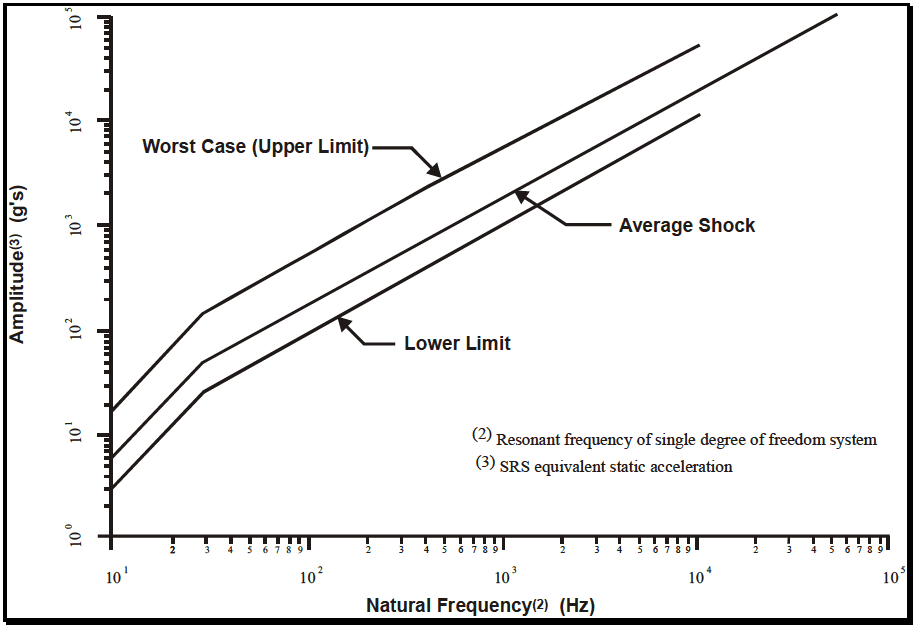
Figure description:
Amplitude(3 (g's vs. Natural Frequency(2 (Hz
Shock Response Spectrum
Legend
- Worst Case (Upper Limit — color: black; symbol: Solid line
- Average Shock — color: black; symbol: Solid line
- Lower Limit — color: black; symbol: Solid line
Annotations
- Worst Case (Upper Limit (text_label - position: Indicated by arrow pointing to the topmost line))
- Average Shock (text_label - position: Indicated by arrow pointing to the middle line)
- Lower Limit (text_label - position: Indicated by arrow pointing to the bottommost line)
- (2 Resonant frequency of single degree of freedom system (text_label - position: Bottom right corner of the chart))
- (3 SRS equivalent static acceleration (text_label - position: Bottom right corner of the chart))
| Natural Frequency(2 (Hz)) | Worst Case (Upper Limit (g's)) | Average Shock (g's) | Lower Limit (g's) |
|---|---|---|---|
| 10 | 16.7 | 5.6 | 2.8 |
| 20 | 66.7 | 22.2 | 11.1 |
| 30 | 150.0 | 50.0 | 25.0 |
| 100 | 500.0 | 166.7 | 83.3 |
| 1000 | 5000.0 | 1666.7 | 833.3 |
| 10000 | 50000.0 | 16666.7 | 8333.3 |
| 20000 | 100000.0 | 33333.3 | null |
| 60000 | null | 100000.0 | null |
Notes: (2 Resonant frequency of single degree of freedom system) (3 SRS equivalent static acceleration
Figure 522.2-1. Shock response spectra of "default" ballistic shock limits (Tables 522.2-I & II).
- d. Procedure IV - Limited Spectrum. Mechanical Shock Simulator. Mechanical shock simulators have been constructed to test very light weight components (0.5 to 1.8 kg (1 to 4 lb) for the smallest machine; higher
MIL-STD-810H
METHOD 522.2
for other contractor machines). These machines produce a shock that lies within the envelope of the default shock response spectrum described in paragraph 2.3.4 up to 10 kHz. Shock content is present above 10 kHz, but it is not well defined. Use of a Mechanical Shock Simulator is less expensive than full spectrum simulation, and may be appropriate for light weight items that are sensitive to shock up to 10 kHz.
- e. Procedure V - Limited Spectrum, Medium Weight Shock Machine (MWSM). Components weighing less than 2273 kg (5000 lb) and not sensitive to frequencies above 1 kHz can be tested over the spectrum from 10 Hz to 1 kHz of Table 522.2-I and Figure 522.2-1 using a MIL-S-901 Medium Weight Shock Machine (MWSM) (paragraph 6.1, reference c) adjusted for 15 mm (0.59 in.) displacement limits. Use of the MWSW may be appropriate for heavy components and subsystems that are shock mounted and/or are not sensitive to high frequencies.
- f. Procedure VI - Drop Table. Light weight components (typically less than 18 kg (40 lbs)) which are shock mounted can often be evaluated for ballistic shock sensitivity at frequencies up to 500 Hz using a drop table. This technique often results in overtest at the low frequencies. The vast majority of components that need shock protection on an armored vehicle can be readily shock mounted. The commonly available drop test machine is the least expensive and most accessible test technique. The shock table produces a half-sine acceleration pulse that differs significantly from ballistic shock. The response of materiel on shock mounts can be enveloped quite well with a half-sine acceleration pulse if an overtest at low frequencies and an undertest at high frequencies is acceptable. Historically, these shortcomings have been acceptable for the majority of ballistic shock qualification testing.
NOTES: Related Shock Tests:
- High Impact / Shipboard Equipment. Perform shock tests for shipboard equipment in accordance with MIL-S-901. The tests of MIL-S-901 are tailorable through the design of the fixture that attaches the test item to the shock machine. Ensure the fixture is as similar to the mounting method used in the actual use environment. High impact shocks for Army armored combat vehicles should be tested using this Method.
- Fuzes and Fuze Components. Perform shock tests for safety and operation of fuzes and fuze components in accordance with MIL-STD-331 (paragraph 6.1, reference d).
- Combined Temperature and Shock Tests. Perform shock tests at standard ambient conditions (Part One, paragraph 5.1a) unless a high or low temperature shock test is required.
2.2.1 Procedure Selection Considerations
Based on the test data requirements, determine which test procedure is applicable. In most cases, the selection of the procedure will be dictated by the actual materiel configuration, carefully noting any gross structural discontinuities that may serve to mitigate the effects of the ballistic shock on the materiel. In some cases, the selection of the procedure will be driven by test practicality. Consider all ballistic shock environments anticipated for the materiel during its life cycle, both in its logistic and operational modes. When selecting procedures, consider:
- a. The Operational Purpose of the Materiel. From the requirements documents, determine the functions to be performed by the materiel either during or after exposure to the ballistic shock environment.
- b. The Natural Exposure Circumstances for Ballistic Shock. The natural exposure circumstances for ballistic shock are based on well-selected scenarios from past experience and the chances of the occurrence of such scenarios. For example, if an armored vehicle is subject to a mine blast, a number of assumptions must be made in order to select an appropriate test for the ballistic shock procedure. In particular, the size of the mine, the location of major pressure wave impact, the location of the materiel relative to the impact “point,” etc. If the armored vehicle is subject to non-penetrating projectile impact, the energy input configuration will be different from that of the mine, as will be the effects of the ballistic shock on the materiel within the armored vehicle. In any case, condition each scenario to estimate the materiel response as a function of amplitude level and frequency content. It will then be necessary to decide to which scenarios to test and which testing is most critical. Some scenario responses may “envelope” others, which may reduce the need
for certain testing such as road, rail, gunfiring, etc. In test planning, do not break up any measured or predicted response to ballistic shock into separate amplitude and/or frequency ranges using different tests to satisfy one procedure.
- c. Required Data. The test data required to determine whether the operational purpose of the materiel has been met.
- d. Procedure Sequence. Refer to paragraph 2.1.2.
2.2.2 Difference Among Procedures
2.2.2.1 Procedure I - BH&T
Ballistic shock is applied in its natural form using live fire testing. Test items are mounted in the BH&T that replicates the full-size vehicle in its “as designed” configuration and location. If required, “upweight” the vehicle to achieve proper dynamic response. Appropriate threats (type, distance, orientation) are successively fired at the hull and/or turret. This procedure is used to evaluate the operation of actual components, or the interaction between various components during actual ballistic impacts. Also, this procedure is used to determine actual shock levels for one particular engagement, that may be above or below the ‘default’ shock level specified in Table 522.2-I.
2.2.2.2 Procedure II - LSBSS
LSBSS is a low cost option for producing the spectrum of ballistic shock without the expense of live fire testing. This procedure is used primarily to test large, hard mounted components at the ‘default’ shock level specified in Table 522.2-I. It produces shock over the entire spectrum (10 Hz to over 100,000 Hz), and is useful in evaluating components of unknown shock sensitivity.
2.2.2.3 Procedure III - LWSM
Ballistic shock is simulated using a hammer impact. The test item is mounted on an anvil table of the shock machine using the test item’s tactical mount. The anvil table receives the direct hammer impact that replicates the lower frequencies of general threats to a hull or turret. This procedure is used to test shock mounted components (up to 113.6 kg (250 lb)), which are known to be insensitive to the higher frequency content of ballistic shock. This procedure produces ‘partial spectrum’ testing (up to 3,000 Hz) at the ‘default’ level specified in Table 522.2-I.
2.2.2.4 Procedure IV - Mechanical Shock Simulator
Ballistic shock is simulated using a metal-to-metal impact (gas driven projectile). The test item is mounted on a plate of the shock machine using the test item’s tactical mount. This procedure is used to test small components (1.8 kg (4 lb)) for the smallest machine; higher weight for other contractor machines), that are known to be insensitive to the highest frequency content of ballistic shock. This procedure produces ‘partial spectrum’ testing (up to 10,000 Hz) at the ‘default’ level specified in Table 522.2-I.
2.2.2.5 Procedure V - MWSM
Ballistic shock is simulated using a hammer impact. The test item is mounted on the anvil table of the shock machine using the test item’s tactical mount. The anvil table receives the direct hammer impact, which replicates the lower frequencies of general threats to a hull or turret. This procedure is used to test components up to 2273 kg (5000 lb) in weight which are known to be insensitive to the higher frequencies of ballistic shock. This procedure produces ‘partial spectrum’ testing (up to 1,000 Hz.) at the ‘default’ level specified in Table 522.2-I.
2.2.2.6 Procedure VI - Drop Table
Ballistic shock is simulated by the impact resulting from a drop. The test item is mounted on the table of a commercial drop machine using the test item’s tactical mounts. The table and test item are dropped from a calculated height. The table receives the direct blow at the impact surface, which approximates the lower frequencies of general threat to a hull or turret. This procedure is used for ‘partial spectrum’ testing of shock mounted components that can withstand an overtest at low frequencies.
2.3 Determine Test Levels and Conditions
Having selected one of the six ballistic shock procedures (based on the materiel’s requirements documents and the tailoring process), complete the tailoring process by identifying appropriate parameter levels, applicable test conditions and applicable test techniques for that procedure. Exercise extreme care in consideration of the details in
the tailoring process. Base these selections on the requirements documents, the Life Cycle Environmental Profile (LCEP), and information provided with this method. Consider the following basic information when selecting test levels.
2.3.1 General Considerations - Terminology
In general, response acceleration will be the experimental variable of measurement for ballistic shock. However, this does not preclude other variables of measurement such as velocity, displacement, or strain from being measured and processed in an analogous manner, as long as the interpretation, capabilities, and limitations of the measurement variable are clear. Pay particular attention to the high frequency environment generated by the ballistic attack, as well as the capabilities of the measurement system to accurately record the materiel’s responses. For the purpose of this method, the terms that follow will be helpful in the discussion relative to analysis of response measurements from ballistic shock testing.
- a. Effective transient duration: The "effective transient duration" is the minimum length of time which contains all significant amplitude time history magnitudes beginning at the noise floor of the instrumentation system just prior to the initial pulse, and proceeding to the point that the amplitude time history is a combination of measurement noise and substantially decayed structural response. In general, an experienced analyst is required to determine the pertinent measurement duration to define the ballistic shock event. The longer the duration of the ballistic shock, the more low frequency information is preserved. The amplitude time history magnitude may be decomposed into several "shocks" with different effective transient durations if it appears that the overall time history trace contains several independent "shock-like" events in which there are decay to near noise floor of the instrumentation system between events. Each event may be considered a separate shock.
- b. Shock response spectrum analysis: Paragraph 6.1, reference e, defines the equivalent static acceleration maximax Shock Response Spectrum (SRS) and provides examples of SRS computed for classical pulses. The SRS value at a given undamped natural oscillator frequency, f n, is defined to be the absolute value of the maximum of the positive and negative acceleration responses of a mass for a given base input to a damped single degree of freedom system. The base input is the measured shock amplitude time history over a specified duration (the specified duration should be the effective transient duration). To some extent, for processing of ballistic shock response data, the equivalent static acceleration maximax SRS has become the primary analysis descriptor. In this measurement description, the maximax equivalent static acceleration values are plotted on the ordinate with the undamped natural frequency of the single degree of freedom system with base input plotted along the abscissa. Interpret the phrase “equivalent static acceleration” literally only for rigid lightweight components on isolation mounts.
2.3.2 Test Conditions – Shock Spectrum Transient Duration and Scaling
Derive the SRS and the effective transient duration, T, from measurements of the materiel's response to a ballistic shock environment or, if available, from dynamically scaled measurements of a similar environment. Because of the inherent very high degree of randomness associated with the response to a ballistic shock, extreme care must be exercised in dynamically scaling a similar environment. For ballistic shock, there are no known scaling laws because of the sensitivity of the response to the size of the shock and the general configuration.
2.3.2.1 Measured Data Available From Ballistic Shock
- a. If measured data are available, the data may be processed utilizing the SRS. (The use of Fourier Spectra (FS) or the Energy Spectral Density (ESD) is not recommended, but may be of interest in special cases.) For engineering and historical purposes, the SRS has become the standard for measured data processing. In the discussion to follow, it will be assumed that the SRS is the processing tool. In general, the maximax SRS spectrum (equivalent static acceleration) is the main quantity of interest. With this background, determine the shock response spectrum required for the test from analysis of the measured environmental acceleration time history. After carefully qualifying the data, to make certain there are no anomalies in the amplitude time histories, according to the recommendations provided in paragraph 6.1, reference f, compute the SRS. The analyses will be performed for Q = 10 at a sequence of natural frequencies at intervals of at least 1/12th octave spacing to span a frequency range consistent with the objective of the procedure.
- b. Because sufficient field data are rarely available for statistical analysis, an increase over the envelope of the available spectral data is sometimes used to establish the required test spectrum to account for variability of
the environment. The degree of increase is based upon engineering judgment and should be supported by rationale for that judgment. In these cases, it is often convenient to envelope the SRS by computing the maximax spectra over the sample spectra and proceed to add a +6 dB margin to the SRS maximax envelope.
NOTE: This approach does not apply to the default values in Table 522.2-I.
2.3.2.2 Measured Data Not Available From Ballistic Shock
If a data base is not available for a particular configuration, use (carefully) configuration similarity and any associated measured data for prescribing a ballistic shock test. Because of the sensitivity of the ballistic shock to the system configuration and the wide variability inherent in ballistic shock measurements, use caution in determining levels. Table 522.2-I and Figure 522.2-1 give ‘default’ values for expected ballistic shock levels when no field measurement results are available.
2.3.3 Ballistic Shock Qualification – Procedure I
Ballistic Shock Qualification - Procedure I is different from the other ballistic shock methods in that the shock levels are unknown until each particular shot (threat munition, attack angle, impact point, armor configuration, etc.) has been fired and measurements have been made. The shock levels are determined by the interaction of the threat munition and the armor as well as by the structure of the vehicle. Although the levels cannot be specified in advance, this technique produces the most realistic shock levels.
2.3.4 Ballistic Shock Qualification – Procedures II Through VI
For Ballistic Shock Procedures II through VI, subject the test item to the appropriate ballistic shock level a minimum of three times in the axis of orientation of greatest shock sensitivity (i.e., the worst direction). Perform an operational verification of the component during/after each test. For frequencies above 1 kHz, many ballistic shock events produce similar shock levels in all three axes. If shock levels are known from previous measurements, the shock testing can be tailored appropriately. If shock measurements are not available, use Steps a-g as outlined below.
- a. Ensure the test item remains in place and that it continues to operate during and following shocks that are at or below the average shock level specified in Table 522.2-I. The test item must also remain in place and continue to operate following shocks that are at or below the worst case shock level specified in Table 522.2- I. Ensure materiel critical to crew survival (e.g., fire suppression systems) continues to operate during and following the worst case shock.
- b. Mount the transducers used to measure the shock on the structure as near as possible to the structure mount. Take triaxial measurements at this location. If triaxial measurements are not practical, make as many uniaxial measurements as is practical.
- c. Analyze the shock measurements in the time domain, as well as the frequency domain. Calculate the SRS using a damping ratio of 5 percent of critical damping (Q = 10); calculate the SRS using at least 12 frequencies per octave, proportionally spaced in the region from 10 Hz to 10 kHz (e.g., 120 frequencies spaced at approximately 10, 10.59, 11.22, 11.89, 12.59, …, 8414, 8913, 9441, 10,000 Hz).
- d. For a test shock to be considered an acceptable simulation of the requirement, 90 percent of the points in the region from 10 Hz to 10 kHz must fall within the bounds listed in Table 522.2-II.
- e. If more than 10 percent of the SRS points in the region from 10 Hz to 10 kHz are above the upper bound, an overtest has occurred. If more than 90 percent of the SRS points lie between the upper and lower bounds, the desired qualification test has occurred. If none of the above occurs, and more than 10 percent of the points are below the lower bound, an undertest has occurred.
- f. If the test item or its mount fails, during a desired or an undertest, redesign the materiel and/or its mount to correct the deficiency.
- g. Retest the redesigned materiel and/or its mount following the above procedure.
MIL-STD-810H
METHOD 522.2
| Boundary | Natural Frequency | |
|---|---|---|
| From 10 to 29.5 Hz | From 29.5 to 10 kHz | |
| Upper Bound | SRS = 0.17020f² | SRS = 5.020f |
| Average Shock (default) | SRS = 0.06033f² | SRS = 1.780f |
| Lower Bound | SRS = 0.03026f² | SRS = 0.8927f |
2.4 Test Item Configuration
- a. General. See Part One, paragraph 5.8.
- b. Specific to this Method. Configure the test item for ballistic shock as would be anticipated during service including particular attention to the details of the mounting of the materiel to the platform.