| Paragraph | Page |
|---|---|
| 1. SCOPE | 1 |
| 1.1 PURPOSE | 1 |
| 1.2 APPLICATION | 1 |
| 1.3 LIMITATIONS | 1 |
| 1.3.1 ACCELERATION | 1 |
| 1.3.2 AERODYNAMIC LOADS | 1 |
| 1.3.3 ACCELERATION VERSUS SHOCK | 1 |
| 1.3.4 CLIMATIC CONDITIONING | 1 |
| 2. TAILORING GUIDANCE | 1 |
| 2.1 SELECTING THE ACCELERATION METHOD | 1 |
| 2.1.1 EFFECTS OF ACCELERATION | 2 |
| 2.1.2 SEQUENCE AMONG OTHER METHODS | 2 |
| 2.2 SELECTING A PROCEDURE | 2 |
| 2.2.1 PROCEDURE SELECTION CONSIDERATIONS | 2 |
| 2.2.2 DIFFERENCE AMONG PROCEDURES | 2 |
| 2.2.2.1 PROCEDURE I - STRUCTURAL TEST | 2 |
| 2.2.2.2 PROCEDURE II - OPERATIONAL TEST | 2 |
| 2.2.2.3 PROCEDURE III - CRASH HAZARD ACCELERATION TEST | 3 |
| 2.2.2.4 PROCEDURE IV - STRENGTH TEST | 3 |
| 2.3 DETERMINE TEST LEVELS AND CONDITIONS | 3 |
| 2.3.1 TEST AXES | 3 |
| 2.3.2 TEST LEVELS AND CONDITIONS - GENERAL | 3 |
| 2.3.3 TEST LEVELS AND CONDITIONS - FIGHTER AND ATTACK AIRCRAFT | 8 |
| 2.4 SPECIAL CONSIDERATIONS | 9 |
| 3. INFORMATION REQUIRED | 10 |
| 3.1 PRETEST | 10 |
| 3.2 DURING TEST | 11 |
| 3.3 POST-TEST | 11 |
| 4. TEST PROCESS | 11 |
| 4.1 TEST FACILITY | 11 |
| 4.2 CONTROLS | 11 |
| 4.2.1 CALIBRATIONS | 11 |
| 4.2.2 TOLERANCES | 11 |
| 4.3 TEST INTERRUPTION | 12 |
| 4.3.1 INTERRUPTION DUE TO LABORATORY EQUIPMENT MALFUNCTION | 12 |
| 4.3.2 INTERRUPTION DUE TO TEST ITEM OPERATION FAILURE | 12 |
| 4.4 TEST SETUP | 12 |
| 4.5 TEST EXECUTION | 12 |
| 4.5.1 PREPARATION FOR TEST | 12 |
| 4.5.1.1 PRETEST STANDARD AMBIENT CHECKOUT | 12 |
| 4.5.1.2 MOUNTING OF THE TEST ITEM | 13 |
| 4.5.2 PROCEDURE I - STRUCTURAL TEST | 14 |
| 4.5.3 PROCEDURE II - OPERATIONAL TEST | 14 |
MIL-STD-810H
METHOD 513.8
CONTENTS - Continued
| Paragraph | Page | |
|---|---|---|
| 4.5.3.1 | CENTRIFUGE | 14 |
| 4.5.3.2 | TRACK/ROCKET POWERED SLED | 14 |
| 4.5.4 | PROCEDURE III - CRASH HAZARD ACCELERATION TEST | 15 |
| 4.5.5 | PROCEDURE IV - STRENGTH TEST | 15 |
| 5. | ANALYSIS OF RESULTS | 15 |
| 5.1 | GENERAL | 15 |
| 5.2 | SPECIFIC TO THIS METHOD. | 15 |
| 5.2.1 | STRUCTURAL TEST | 15 |
| 5.2.2 | OPERATIONAL TEST | 16 |
| 5.2.3 | CRASH HAZARD ACCELERATION TEST | 16 |
| 5.2.4 | STRENGTH TEST | 16 |
| 6. | REFERENCE/RELATED DOCUMENTS. | 16 |
| 6.1 | REFERENCED DOCUMENTS | 16 |
| 6.2 | RELATED DOCUMENTS.. | 16 |
TABLES
| TABLE 513.8-I. | SUGGESTED G LEVELS FOR PROCEDURE I - STRUCTURAL TEST. | 4 |
| TABLE 513.8-II. | SUGGESTED G LEVELS FOR PROCEDURE II - OPERATIONAL TEST | 5 |
| TABLE 513.8-III. | SUGGESTED G LEVELS FOR PROCEDURE III - CRASH HAZARD ACCELERATION TEST. | 6 |
| TABLE 513.8-IV. | SYSTEM SPECIFIC G LEVELS FOR PROCEDURE III- CRASH HAZARD ACCELERATION TEST | 7 |
FIGURES
| FIGURE 513.8-1. | EXAMPLE SINE BURST TEST SPECIFICATION FOR STRENGTH TESTING | 8 |
| FIGURE 513.8-2. | TYPICAL DIRECTIONS OF VEHICLE ACCELERATION (RIGHT HAND RULE). | 8 |
METHOD
513.8 ANNEX A TEST CONSIDERATIONS
| 1. | TEST ITEM MOUNTING FIXTURE | .A-1 |
| 1.1 | FIXTURE DESIGN CONSIDERATIONS. | .A-1 |
| 1.2 | FIXTURE MATERIALS AND CONSTRUCTION. | .A-5 |
| 1.3 | GENERAL CONSIDERATIONS IN CENTRIFUGE TESTING. | .A-5 |
| 2. | FAILURE DETECTION PROBLEMS. | ..A-6 |
| 3. | ACCELERATION AND FORCE CALCULATION | ..A-6 |
FIGURES
| FIGURE 513.8A-1. | BASIC CENTRIFUGE TEST INSTALLATION RESULTING COMPRESSIVE LOAD CONDITIONS | A-2 |
| FIGURE 513.8A-2. | A TYPICAL CENTRIFUGE TEST INSTALLATION REQUIRING CONSIDERATION OF MOMENT EFFECTS IN INSTALLATION DESIGN | A-3 |
| FIGURE 513.8A-3. | BASIC CENTRIFUGE TEST INSTALLATION RESULTING IN TENSILE LOAD CONDITIONS | A-4 |
| FIGURE 513.8A-4. | BASIC FORCES IMPOSED ON TEST ITEM DUE TO ACCELERATIONS PRODUCED BY CENTRIFUGE | A-7 |
MIL-STD-810H
METHOD 513.8
METHOD
513.8 ACCELERATION
NOTE: Tailoring is essential. Select methods, procedures and parameter levels based on the tailoring process described in Part One, paragraph 4.2.2, and Annex C. Apply the general guidelines for laboratory test methods described in Part One, paragraph 5 of this Standard.
513.8 ANNEX A METHOD 513.8, ANNEX A TEST CONSIDERATIONS
513.8 ANNEX A
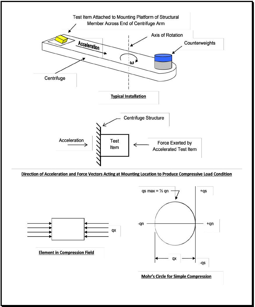
Figure description:
Key Information:
- Subject: Basic centrifuge test installation designed to produce compressive load conditions, per MIL-STD-810H.
- Typical Installation Components:
- Centrifuge Arm: Rotating structure holding the test setup.
- Test Item: Attached to a mounting platform at the end of the arm.
- Counterweights: Positioned on the opposite side of the axis of rotation to balance the arm.
- Axis of Rotation: The central pivot point for angular velocity (.
- Loading Mechanics:
- Acceleration: Directed inward toward the axis of rotation.
- Force Vector: The accelerated test item exerts an outward force against the centrifuge structure, resulting in a compressive load.
- Stress Analysis Models:
- Element in Compression Field: Displays the compressive forces ( acting on a test element.
- Mohr’s Circle for Simple Compression: Graphically represents the state of stress, indicating that maximum shear stress ( is equal to half of the normal stress (.
Figure 513.8A-1. Basic centrifuge test installation resulting in compressive load conditions.
MIL-STD-810H
METHOD 513.8 ANNEX A
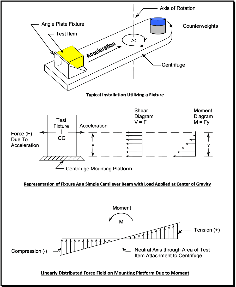
Figure description:
Centrifuge Test Installation Principles (MIL-STD-810H, Figure 513.8A-2
Key Components & Setup
- Centrifuge: Rotating arm system for acceleration testing.
- Axis of Rotation: The central point around which the centrifuge rotates (.
- Test Item: The object being tested, mounted on an Angle Plate Fixture.
- Counterweights: Positioned opposite the test item to balance the rotating mass.
- Acceleration: Directed radially outward from the axis of rotation.
Structural Analysis Representations
- Simple Cantilever Beam Model: Represents the fixture with a load applied at the Center of Gravity (CG.
- Force (F: Resultant force due to acceleration.
- Shear Diagram (: Uniform shear force along the height (.
- Moment Diagram (: Moment increases linearly with distance ( from the applied load to the mounting platform.
- Linearly Distributed Force Field: Shows the effect of the moment ( on the mounting platform.
- Neutral Axis: The center line through the attachment area where force is zero.
- Compression (-: Force acting downward on one side of the attachment.
- Tension (+: Force acting upward on the opposite side of the attachment.
Figure 513.8A-2. A typical centrifuge test installation requiring consideration of moment effects in installation design.
MIL-STD-810H METHOD 513.8 ANNEX A
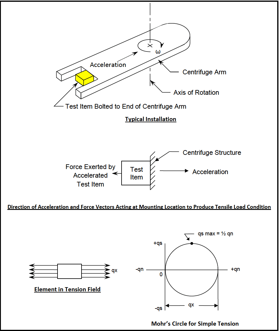
Figure description:
Centrifuge Testing Mechanical Analysis and Stress Representation
Typical Installation
| Component | Label / Description |
|---|---|
| Centrifuge Arm | Rotating arm structure |
| Axis of Rotation | Central point of rotation marked with 'x' and angular velocity 'ω' |
| Acceleration | Radial vector pointing from the test item toward the axis of rotation |
| Test Item | Item undergoing test, bolted to the end of the centrifuge arm |
Direction of Acceleration and Force Vectors Acting at Mounting Location to Produce Tensile Load Condition
Annotations
- Force Exerted by Accelerated Test Item (vector_label - position: Left of test item)
- Acceleration (vector_label - position: Right of test item)
| Entity | Vector / Label | Direction |
|---|---|---|
| Test Item | Force Exerted by Accelerated Test Item | Left (outward) |
| Test Item | Acceleration | Right (toward axis) |
| Centrifuge Structure | Mounting surface | Attached to the right side of the test item |
| Condition | Tensile Load Condition | Resulting state of the mounting |
Mohr's Circle for Simple Tension
Annotations
- qs max = 1/2 qn (text_label - position: Top of Mohr's circle)
- qx (dimension_line - position: Horizontal diameter from 0 to +qn)
- Element in Tension Field (text_label - position: Located to the left of the Mohr's circle)
- -qn (text_label - position: Negative side of horizontal axis)
| Parameter | Axis Label / Variable | Value / Coordinate |
|---|---|---|
| Applied Normal Stress | qx | Diameter of Mohr's circle |
| Normal Stress Axis | qn | Horizontal axis |
| Shear Stress Axis | qs | Vertical axis |
| Origin (Left Edge) | 0 | (0, 0) |
| Maximum Normal Stress | +qn | qx |
| Maximum Shear Stress | qs max | 1/2 qn |
| Center of Circle | - | (qx/2, 0) |
Notes: The figure illustrates the relationship between centrifuge rotation, induced acceleration, and the resulting tensile stress state in a test item, represented both as a physical element and a Mohr's circle plot.
513.8A-3. Basic centrifuge test installation resulting in tensile load conditions.
MIL-STD-810H
METHOD 513.8 ANNEX A
Occasionally, the design of a centrifuge test installation may require that the bracketry weight be kept at a minimum so that the total installation load does not exceed the centrifuge load limits. This, as in other areas of structural design, may require a careful investigation of various combinations of stress at critical locations. The complexity of the load conditions is dependent upon the centrifuge test requirements as well as the configuration of the test item and the bracketry by which the test item is attached to the centrifuge. Test conditions and the installation may be such that only simple bracketry loading involving shear, tension, or compression requires consideration, or the test may be such that various loading conditions exist with combined stresses that vary with time. An analysis of the more complex loading conditions may require investigation of the state of stress and strain, and the deflection due to distributed forces or force fields. The use of experimental, as well as analytical, analysis tools may be necessary to obtain an analysis in sufficient detail. Standard strength-of-materials references are adequate for most of the structural design required in conjunction with centrifuge testing. Some typical centrifuge test item installations and the basic bracketry load and stress considerations are shown in Figures 513.8A-1, 513.8A-2, and 513.8A-3.
513.8 ANNEX A
significantly large. If test specifications require a rapid g level ramp rate within the limits attainable on a centrifuge, it may be necessary to provide a means of accounting for large tangential acceleration values at the test item location. There have been designs that allow the test item to be rotated relative to the centrifuge arm in such a way that the resultant of the normal and tangential acceleration vectors remains orientated along the desired axis of the test object during periods when a change in centrifuge rotational speed occurs. Figure 513.8A-4 depicts the forces due to rotation and change in rotational speed of the centrifuge.