523.4-3 TEST CONFIGURATION
Figure 523.4A-7 is a schematic of the arrangements of a typical set of apparatus for performing a vibro- acoustic/temperature test. This arrangement consists of a control room that may be remotely located from a hardware test chamber termed an acoustic cell. The electrodynamic or electrohydraulic shakers are hidden under the test items.
MIL-STD-810H METHOD 523.4, ANNEX A
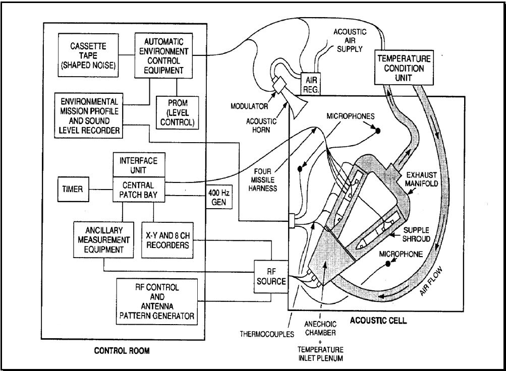
Figure description:
System: MIL-STD-810H Method 523.4, Typical Test Apparatus Arrangement.
Control Room Components:
- Control/Signal Generation: Cassette tape (shaped noise, automatic environment control equipment, PROM (level control, 400 Hz generator, RF control, and antenna pattern generator.
- Recording/Monitoring: Environmental mission profile and sound level recorder, X-Y and 8-channel recorders, ancillary measurement equipment, and timer.
- Routing: Interface unit and central patch bay.
Acoustic Cell Components:
- Acoustic Simulation: Acoustic air supply, air regulator, modulator, and acoustic horn.
- Thermal/Environmental Simulation: Temperature condition unit, air flow path, temperature inlet plenum, anechoic chamber, supple shroud, and exhaust manifold.
- Instrumentation/Interface: Microphones, thermocouples, and four missile harness.
- External Input: RF Source.
Figure 523.4A-7. Typical arrangement of test apparatus.
MIL-STD-810H METHOD
3.1 Pretest
The following information is required to conduct a vibro-acoustic/temperature test:
- a. General. Information listed in Part One, paragraphs 5.7, 5.8, and 5.9; and Part One, Annex A, Task 405 of this standard.
- b. Specific to this method.
- (1) A written, step-by-step procedure for conduct of the test that implements the test plan. Include the recording and documenting of test events and measurements. It may include other existing procedures by reference; but explicitly include any procedures related to safety.
- (2) Quantity of items to be tested.
- (3) Composite mission profile. Include in the detailed environmental test plan (DETP) (either directly or by reference), information used in designing the composite mission profile. Include the following:
- (a) The particular environmental and operational variables to be controlled in the test (a minimum set includes vibration level, vibration spectrum, skin temperature, and duty cycle).
- (b) The mission profiles, including aircraft types, store load, and percentage of occurrence of different missions.
- (c) The climatic region of operation and the distribution of ambient temperatures.
- (d) Derivation of the composite mission profile; including captive flight vibration measurements, temperature measurements, and thermal models.
- (4) Test cycle. The test cycle defines the time history of the controlled and monitored variables and the performance of functional tests. The environmental test cycle is the product of a composite mission cycle and a climatic offset cycle.
- (a) Composite mission cycle. This is a time history of the environmental and operating stresses to be imposed repeatedly at different offset climatic temperatures. All functional tests and other events such as shocks are identified in this time history. The duration, level, and other characteristics of
MIL-STD-810H
METHOD 523.4
each stress are defined. Include in this cycle, transitional periods to normalize temperatures between climatic offsets.
- (b) Environmental profile charts. Use a chart (either graph or table) for each of the environmental variables to be controlled or monitored during the test that shows the intended value for the variable during the composite mission cycle. These charts will be for the standard-day diurnal temperature condition.
- (c) Climatic offset table. Prepare a table of the temperature offsets in their order of application to successive composite mission cycles. Explain in the DETP the origin of these offsets and their scope (e.g., 95 percent worldwide). Also, include any transitional temperature conditioning periods between composite mission cycles.
- (d) Test control method. Include in the DETP, the method to be used in controlling environmental stresses, the location and type of sensors, the use of open-loop or closed-loop control, and the tolerances for variables.
- (5) Test completion criteria. Specific statement of what constitutes a complete test (e.g., number or type of failures, number of test cycles completed, etc.).
- (6) Test log. Use a test log for written information and recording unusual events and anomalies. As a minimum, include the following:
- (a) Time that the test item(s) is installed in the test facility and the number of the first composite mission cycle thereafter.
- (b) Calibration of instrumentation and apparatus.
c. Tailoring. Necessary variations in the basic test procedures to accommodate LCEP requirements.
3.2 During Test
Collect the following information while conducting the test:
- a. General. Information listed in Part One, paragraphs 5.10 and 5.12, and in Annex A, Tasks 405 and 406, of this standard.
- b. Specific to this method.
- (1) A chronological record of events. Record all events that affect the test or interpretation of test results.
- (2) A continuous record of environmental levels. Running record of all ambient and test environmental factors and levels. For example, room temperature and humidity, acoustic horns and shaker levels, skin and component temperatures, buffet events, shaker shock events, etc.
- (3) A record of deviations. Chronological record of all deviations from intended levels and/or durations of test environments.
- (4) Failure interpretation/disposition. Procedures for operations after failures occur, including fix, repair, and test restart.
3.3 Post-Test
The following post test data shall be included in the test report.
-
a. General. Information listed in Part One, paragraph 5.13, and in Part One, Annex A, Task 406 of this standard.
-
b. Specific to this method.
-
(1) Test chronology. Listing of events, test interruptions, and test failures.
-
(2) Failure interpretation/disposition. Definitions of failures and failure categories. Procedures for operations after failures occur including fix, repair, and test restart.
-
(3) Test item disposition. Location, condition, and planned uses of the test item (e.g., returned to the manufacturer, held for further tests, etc.).