505.7-2 IRRADIANCE AND SPECTRAL DISTRIBUTION
The effect of radiation on the materiel will depend mainly on the level of irradiance and its spectral distribution.
2.1 Selecting this Method
After examining requirements documents, review of the LCEP, and applying the tailoring process in Part One of this Standard to determine where solar radiation effects are foreseen in the life cycle of the test item, use the following to confirm the need for this Method and to place it in sequence with other methods.
505.7-2.1 Irradiance
The irradiance by the sun on a plane perpendicular to the incident radiation outside the Earth's atmosphere at the mean Earth-Sun distance is known as the solar constant “I0.” The irradiance at the surface of the Earth is the result of the solar constant and the influence of attenuation and scattering of radiation in the atmosphere. For test purposes, a maximum intensity of 1120 W/m2 is specified to simulate the global (total) radiation at the surface of the Earth from the Sun and the sky with the Sun at zenith, based on a solar constant I0 = 1350 W/m2. The true solar constant is thought to be about 1365-1370 W/m2.
2.1.1 Effects of Solar Radiation Environments
2.1.1.1 Heating Effects
The heating effects of solar radiation differ from those of high air temperature alone in that solar radiation generates directional heating and thermal gradients. In the solar radiation test, the amount of heat absorbed or reflected depends primarily on the absorptive or reflective surface properties (e.g., roughness, color, etc.) on which the radiation is incident. If a glazing system (glass, clear plastic, or translucent media, e.g., windshield) is part of the test item configuration, and the component of concern is exposed to solar energy that has passed through the glazing system, use a full spectrum source. In addition to the differential expansion between dissimilar materials, changes in the
intensity of solar radiation may cause components to expand or contract at different rates that can lead to severe stresses and loss of structural integrity. In addition to those identified in Method 501.7, consider the following typical problems to help determine if this Method is appropriate for the materiel being tested. This list is not intended to be all-inclusive.
- a. Jamming or loosening of moving parts.
- b. Weakening of solder joints and glued parts.
- c. Changes in strength and elasticity.
- d. Loss of calibration or malfunction of linkage devices.
- e. Loss of seal integrity.
- f. Changes in electrical or electronic components.
- g. Premature actuation of electrical contacts.
- h. Changes in characteristics of elastomers and polymers.
- i. Blistering, peeling, and de-lamination of paints, composites, and surface laminates applied with adhesives such as radar absorbent material (RAM).
- j. Softening of potting compounds.
- k. Pressure variations.
- Sweating of composite materials and explosives.
- m. Difficulty in handling.
2.1.1.2 Actinic Effects
In addition to the heating effects of paragraph 2.1.1.1, certain degradation from solar energy may be attributable to other portions of the spectrum, particularly the ultraviolet. Since the rate at which these reactions will occur generally increases as the temperature rises, use the full spectrum to adequately simulate the actinic effects of solar radiation. The following are examples of deterioration caused by actinic effects. The list is not intended to be comprehensive.
- a. Fading of fabric and plastic color.
- b. Checking, chalking, and fading of paints.
- c. Deterioration of natural and synthetic elastomers and polymers through photochemical reactions initiated by shorter wavelength radiation. (High strength polymers such as Kevlar are noticeably affected by the visible spectrum. Deterioration and loss of strength can be driven by breakage of high-order bonds (such as pi and sigma bonds existing in carbon chain polymers) by radiation exposure.)
2.1.2 Sequence Among Other Methods
- a. General. Use the anticipated life cycle sequence of events as a general sequence guide (see Part One, paragraph 5.5).
- b. Unique to this Method. Generally, consider applying the solar radiation test at any stage in the test program. However, high temperatures or actinic effects could affect material's strength or dimensions that could affect the results of subsequent tests such as vibration.
2.2 Selecting Procedures
This Method includes two test procedures: Procedure I (Cycling for heating effects) and Procedure II (Steady State for actinic effects). Determine the procedure(s) to be used.
505.7-2.2 Spectral Distribution - Sea Level versus High Altitude
At high altitude, solar radiation contains a greater proportion of damaging UV radiation than at sea level. The internationally-agreed spectrum (see Table 505.7-I) recommended for general testing is a representation of the real environment at sea level. This spectrum is recommended for use at both sea level and at high altitude.
2.2.1 Procedure Selection Considerations
When selecting procedures, consider:
- a. The operational purpose of the test item. Physical degradation that occurs during exposure may produce adverse effects on materiel performance or reliability. Based on the purpose of the materiel, determine functional modes and test data needed to evaluate the performance of the test item during and after exposure to solar radiation.
MIL-STD-810H
METHOD 505.7
- b. The anticipated areas of deployment.
- c. The test item configuration.
- d. The anticipated exposure circumstances (use, transportation, storage, etc.).
- e. The expected duration of exposure to solar radiation.
- f. The expected problem areas within the test item.
Caution: When temperature conditioning, ensure the total test time at the most severe temperature does not exceed the life expectancy of any material (see Part One, paragraph 5.19).
2.2.2 Difference Between Procedures
While both procedures involve exposing test items to simulated solar radiation, they differ on the basis of timing and level of solar loads. Procedure I is designed to determine the heat produced by solar radiation, and effects of that heat by exposing materiel to continuous 24-hour cycles of simulated solar radiation (or thermal loading) at realistic maximum levels typical throughout the world. Procedure II (Steady State (actinic effects)) is designed to accelerate photo degradation effects produced by solar radiation. This procedure exposes materiel to cycles of intensified solar loads (approximately 2.5 times normal levels) interspersed with dark periods to accelerate actinic effects that would be accumulated over a longer period of time under normal solar loads. Actual acceleration ratios are material dependent, and 2.5 times the natural solar exposure may not provide equal acceleration. This could, however, provide a more rapid test provided the failure mechanisms follow the path expected in the real environment. The key to using either procedure successfully is maintaining enough airflow to prevent the test item from exceeding temperatures that would be attained under natural conditions. Therefore, prior to conducting Procedure II, the maximum response temperature from procedure I or field/fleet data must be known. However, do not use so much airflow that it produces unrealistic cooling.
- a. Procedure I – Cycling (heating and/or minimal actinic effects). Use Procedure I to investigate response temperatures when materiel is exposed in the open in realistically hot climates, and is expected to perform without degradation during and after exposure. Although Procedure I can be performed using simple heat-generating lamps (providing the guidance in paragraph 4.1.2 is followed), limited evaluation of actinic effects is possible if full spectrum lamps are used instead. It is preferable to use the solar radiation test (as opposed to the High Temperature test, Method 501.7) when the materiel could be affected by differential heating (see paragraph 2.1.1.1), or when the levels or mechanisms of heating caused by solar radiation are unknown (this encompasses almost all materiel).
- b. Procedure II – Steady State (actinic effects). Use Procedure II to investigate the effects on materiel of long periods of exposure to sunshine. Actinic effects usually do not occur until materiel surfaces receive large amounts of sunlight (as well as heat and moisture). Therefore, it is inefficient to use the repeated, long cycles of normal levels of solar radiation (as in Procedure I) to generate actinic effects. Using Procedure I for this purpose could take months. The approach, therefore, is to use an accelerated test that is designed to reduce the time to reproduce cumulative effects of long periods of exposure. The 4-hour "lights-off" period of each 24-hour cycle allows for test item conditions (physical and chemical) to return toward "normal" and provide some degree of thermal stress exercising. The key to using Procedure II successfully is maintaining enough cooling air to prevent the test item from exceeding peak response temperatures that would be attained under natural conditions or Procedure I.
MIL-STD-81 METHOD 50
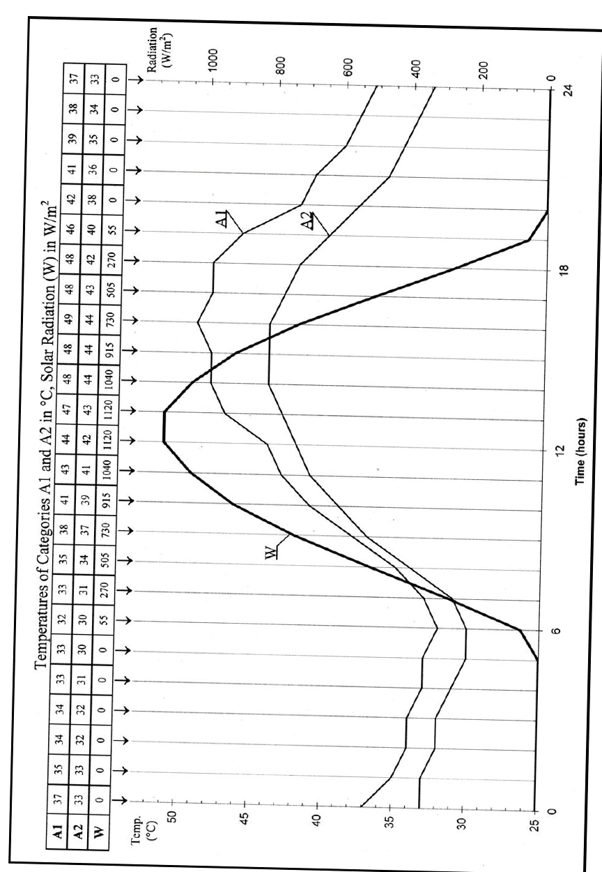
Figure description:
Temperatures of Categories A1 and A2 in °C, Solar Radiation (W in W/m²
Temperatures of Categories A1 and A2 in °C, Solar Radiation (W in W/m²
Legend
- Category A1 (°C — color: black; symbol: Thin solid line
- Category A2 (°C — color: black; symbol: Thin solid line
- Solar Radiation W (W/m² — color: black; symbol: Thick solid line
Annotations
- A1 (text_label - position: at approximately (16, 49 relative to the left axes))
- A2 (text_label - position: at approximately (17, 43 relative to the left axes))
- W (text_label - position: at approximately (10, 40 relative to the left axes))
| Time (hours) | Category A1 (°C) | Category A2 (°C) | Solar Radiation W (W/m²) |
|---|---|---|---|
| 0 | 37 | 33 | 0 |
| 1 | 35 | 33 | 0 |
| 2 | 34 | 32 | 0 |
| 3 | 34 | 32 | 0 |
| 4 | 33 | 31 | 0 |
| 5 | 33 | 30 | 0 |
| 6 | 32 | 30 | 55 |
| 7 | 33 | 31 | 270 |
| 8 | 35 | 34 | 505 |
| 9 | 38 | 37 | 730 |
| 10 | 41 | 39 | 915 |
| 11 | 43 | 41 | 1040 |
| 12 | 44 | 42 | 1120 |
| 13 | 47 | 43 | 1120 |
| 14 | 48 | 44 | 1040 |
| 15 | 48 | 44 | 915 |
| 16 | 49 | 44 | 730 |
| 17 | 48 | 43 | 505 |
| 18 | 48 | 42 | 270 |
| 19 | 46 | 40 | 55 |
| 20 | 42 | 38 | 0 |
| 21 | 41 | 36 | 0 |
| 22 | 39 | 35 | 0 |
| 23 | 38 | 34 | 0 |
| 24 | 37 | 33 | 0 |
Notes: The data values are explicitly listed in a table at the top of the chart. The chart features a dual Y-axis system: the left axis measures Temperature (°C from 25 to 50, and the right axis measures Solar Radiation (W/m² from 0 to 1000+. The time axis covers a full 24-hour cycle.))
MIL-STD-81
METHOD 50
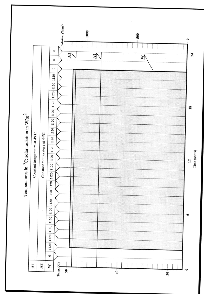
Figure description:
Temperatures in °C; solar radiation in W/m²
Temperatures in °C; solar radiation in W/m²
Legend
- A1: Constant temperature at 49°C — color: black; symbol: Horizontal line
- A2: Constant temperature at 44°C — color: black; symbol: Horizontal line
- W: Solar radiation in W/m² — color: gray; symbol: Shaded region
Annotations
- Constant temperature at 49°C (A1 (horizontal_line - position: y = 49 (Left axis)))
- Constant temperature at 44°C (A2 (horizontal_line - position: y = 44 (Left axis)))
- Solar Radiation (W (shaded_area - position: y = 1120 (Right axis from hour 1 to 21)))
| Time (hours) | Temperature A1 (°C) | Temperature A2 (°C) | Radiation W (W/m²) |
|---|---|---|---|
| 0 | 49 | 44 | 0 |
| 1 | 49 | 44 | 1120 |
| 2 | 49 | 44 | 1120 |
| 3 | 49 | 44 | 1120 |
| 4 | 49 | 44 | 1120 |
| 5 | 49 | 44 | 1120 |
| 6 | 49 | 44 | 1120 |
| 7 | 49 | 44 | 1120 |
| 8 | 49 | 44 | 1120 |
| 9 | 49 | 44 | 1120 |
| 10 | 49 | 44 | 1120 |
| 11 | 49 | 44 | 1120 |
| 12 | 49 | 44 | 1120 |
| 13 | 49 | 44 | 1120 |
| 14 | 49 | 44 | 1120 |
| 15 | 49 | 44 | 1120 |
| 16 | 49 | 44 | 1120 |
| 17 | 49 | 44 | 1120 |
| 18 | 49 | 44 | 1120 |
| 19 | 49 | 44 | 1120 |
| 20 | 49 | 44 | 1120 |
| 21 | 49 | 44 | 0 |
| 22 | 49 | 44 | 0 |
| 23 | 49 | 44 | 0 |
| 24 | 49 | 44 | 0 |
Notes: The chart shows a 24-hour test cycle where temperatures A1 and A2 are kept constant at 49°C and 44°C respectively, while solar radiation (W follows a step function profile, maintaining 1120 W/m² for 20 hours (from hour 1 to hour 21 and remaining at 0 W/m² for the rest of the cycle.))
MIL-STD-810H
METHOD 505.7
2.3 Determine Test Levels and Conditions
Having selected this Method and relevant procedures (based on the materiel's requirements documents and the tailoring process), complete the tailoring process by identifying appropriate parameter levels, special test conditions and techniques for these procedures such as the diurnal cycle, test duration, test item configuration, relative humidity, and any additional appropriate conditions. Base these test parameter levels on the Life Cycle Environmental Profile (LCEP – Part One Task 402), requirements documents (see Part One, Figure 1-1), and information provided with this Method. Consider the following in light of the operational purpose and life cycle of the materiel.
2.3.1 Climatic Conditions
For Procedure I, there are two high temperature diurnal cycles included that correspond to the maximum meteorological conditions in the two climatic categories, A1 and A2 of MIL-HDBK-310 (paragraph 6.1, reference a). Figure 505.7-1 shows the daily cycles of temperature and solar radiation corresponding to categories A1 and A2 for Procedure I. Choose the conditions for the test according to the planned climatic categories for use of the materiel:
- a. Worldwide deployment. Cycle A1 has peak conditions of 1120 W/m² (355 BTU/ft²/hr) and 49 °C (120 °F) (but not occurring at the same time of day), and is normally accompanied by some degree of naturally occurring winds. It represents the hottest conditions exceeded not more than one percent of the hours in the most extreme month at the most severe locations that experience very high temperatures accompanied by high levels of solar radiation, namely, hot, dry deserts of north Africa, southwest and south central Asia, central and western Australia, northwestern Mexico, and the southwestern USA.
- b. Cycle A2 has peak conditions of 1120 W/m² and 43 °C (110 °F) (but not occurring at the same time of day) and represents less severe conditions at locations that experience high temperatures accompanied by high levels of solar radiation, winds, and moderately low humidity, namely, the most southerly parts of Europe, most of the Australian continent, south central Asia, northern and eastern Africa, coastal regions of north Africa, southern parts of the US, and most of Mexico. Use this cycle when the materiel is to be used only in geographical locations described in category A2, but not in category A1.
- c. Figure 505.7-2 shows the corresponding temperature and solar radiation levels for Procedure II.
2.3.2 Test Duration
- a. Procedure I. Expose the test item to continuous 24-hour cycles of controlled simulated solar radiation and temperature as indicated on Figure 505.7-1 or as identified in the requirements documents. A goal of this test is to establish the highest temperature that the test item will reach during repeated cycles. Perform at least three continuous cycles. If the maximum of the peak response temperature of the previous 24-hour cycle) is not reached (±2 °C (±3.6 °F)) during three cycles, continue the cycles until repeated peak temperatures are reached, or for seven cycles, whichever comes first. In the absence of other guidance, the maximum test duration of seven cycles was chosen because the peak high temperature for the selected climatic region occurs approximately one hour in each of seven cycles in the most extreme month. If more exact simulation is required, consult meteorological data for the particular areas under consideration. This may include adjustment of solar energy, if appropriate, to account for latitude, altitude, month of anticipated exposure, or other factors (for example, a product exclusively used in northern areas, or exclusively used in winter months). Any deviation from the standard conditions must be detailed and justified in the test report.
- b. Procedure II. Procedure II produces an acceleration factor of approximately 2.5 as far as the total energy received by the test item is concerned, i.e., one 24-hour cycle as shown on Figure 505.7-2 provides approximately 2.5 times the solar energy experienced in one 24-hour (natural) diurnal cycle plus a 4-hour lights-off period to allow for alternating thermal stressing and for the so-called "dark" processes to occur. To simulate 10 days of natural exposure, for instance, perform four 24-hour cycles as shown on Figure 505.7-2. Recommend ten 24-hour cycles (as on Figure 505.7-2) for materiel that is occasionally used outdoors, such as portable test items, etc. For materiel continuously exposed to outdoor conditions, recommend 56 or more 24-hour cycles. Do not increase the irradiance above the identified level. Presently there is no indication that attempting to accelerate the test in this way gives results that correlate with materiel response under natural solar radiation conditions.
2.3.3 Humidity
Various levels of relative humidity occur naturally, and humidity combined with temperature and solar radiation can, in many cases, have deleterious effects on materiel. If the materiel is known or suspected to be sensitive to RH,
MIL-STD-810H
METHOD 505.7
include it in the Procedure I test requirements. MIL-HDBK-310 and NATO STANAG 4370, AECTP 230, (paragraph 6.1, references a and b) have temperature-humidity data for various regions of the Earth.
2.3.4 Configuration
- a. Use the same test item configuration as during exposure to natural solar radiation. The orientation of the test item relative to the direction of radiation will have a significant impact on the heating effects. In cases where several test item components are already known to be sensitive to solar effects, consider adjusting the relative test item/solar radiation source orientation to simulate a natural diurnal cycle. Whenever possible, mount the test item so that its configuration is representative of actual deployment, as provided in the requirements document. This mounting may include supports or a substrate of specified properties (e.g., a layer of concrete of specified thickness or a sand bed of certain reflectivity). (See paragraph 4.1.1.)
- b. Surface contamination. Dust and other surface contamination may significantly change the absorption characteristics of irradiated surfaces. Unless otherwise required, ensure the test items are clean when tested. However, if the effects of surface contamination are to be assessed, include in the relevant requirements document the necessary information on preparation of surfaces.
2.3.5 Spectral Power Distribution - Sea Level versus High Ground Elevations
At high ground elevations solar radiation contains a greater proportion of damaging UV radiation than at sea level. Although the internationally agreed spectrum shown in Table 505.7-I is recommended for general testing, it is a closer representation of the real environment at sea level. This standard spectrum may be used (unless other data are available) for both sea level and high ground elevations.
| Spectral Region | Bandwidth (nm) | Natural Radiation (% of total) | Tolerance (% of total) | Irradiance (W/m²) | Spectral Region Irradiance (W/m²) | |
|---|---|---|---|---|---|---|
| Min | Max | |||||
| Ultraviolet - B | 280-320 | 0.5 | 0.3 | 0.7 | 5.6 | 5.6 |
| Ultraviolet - A | 320-360 | 2.4 | 1.8 | 3 | 26.9 | 62.7 |
| 360-400 | 3.2 | 2.4 | 4.4 | 35.8 | ||
| Visible | 400-520 | 17.9 | 16.1 | 19.7 | 200.5 | 580.2 |
| 520-640 | 16.6 | 14.9 | 18.3 | 185.9 | ||
| 640-800 | 17.3 | 12.8 | 19 | 193.8 | ||
| Infrared | 800-3000 | 42.1 | 33.7 | 50.5 | 471.5 | 471.5 |
| Totals | 1120 | 1120 | ||||
NOTE: The amount of radiation wavelength shorter than 300 nm reaching the Earth's surface is small but the effect on the degradation of material can be significant. Short wavelength energy below 300 nm can cause materials to fail unnecessarily (if not present in the natural exposure). In reverse, if energy below 300 nm is present in the natural environment and not present in the accelerated exposure, material that should fail may pass the test. This is entirely material dependent because it relates to the end use in natural exposure. Values in the above table have been taken from DIN 75220. (See Annex A, paragraph 2.2.)
2.3.6 Temperature
In addition to the temperature guidance given elsewhere in this Method, it is essential to maintain the air temperature in the vicinity of the test item to that in the respective profile (A1 or A2) or as specified in the test plan. To do so requires necessary airflow and air temperature measurement (sensors shielded from radiation) in the immediate vicinity of the test item. See Annex A, paragraph 5.2 for temperature measurement guidance.
2.3.7 Airflow
The key to using this Method successfully is maintaining enough airflow to obtain the test item peak response temperatures that would be attained under natural conditions.
For Procedure I, use an airspeed of 1.5 to 3.0 m/sec (300 to 600 ft/min) unless otherwise specified. If the deployed environment will subject the item to either limited or no wind speed (shielded from natural wind), then use a minimum air speed, no less than 0.25 m/sec (50 ft/min), when conducting Procedure I. Generally, an airflow of as little as 1 m/s
MIL-STD-810H
METHOD 505.7
(200 ft/min) can cause a reduction in temperature rise of over 20 percent as compared to still air. To ensure test repeatability, the air speed must be measured and recorded in the test report.
For Procedure II, use the minimum required airspeed required to maintain the thermal response as measured in the natural environment or Procedure I. This implies that before this test can be performed, the maximum temperature response the materiel would experience under natural conditions (by using field/fleet data or as determined by running Procedure I) must be known. However, do not use so much cooling air that it produces unrealistic cooling. Similarly, if multiple and identical test items are to be tested, use one or more of the items for the preliminary test to determine the maximum temperature response. Since actinic effects are highly dependent upon the solar radiation spectrum (as well as intensity and duration), the spectrum must be as close as possible to that of natural sunlight (see Table 505.7-I).
2.4 Test Item Operation
When it is necessary to operate the test item, use the following guidelines for establishing test operating procedures.
WARNING: If the sheltered environment is intended to be occupied by personnel during exposure to high temperature, it is recommended that sensors are installed to detect VOCs, CO, and Phthalates due to potential out-gassing.
- a. General. See Part One, paragraph 5.8.2.
- b. Unique to this Method.
- (1) Include operating modes that consume the most power (generate the most heat).
- (2) Include the required range of input voltage conditions, if changes in voltage could affect the test item thermal dissipation or response (e.g., power generation or fan speed).
- (3) Introduce any cooling media that normally would be applied during service use (e.g., forced air or liquid coolant). Consider using cooling medium inlet temperatures and flow rates that represent both typical and worst-case degraded temperature and flow conditions.