515.8-1 BROADBAND RANDOM AND INCIDENCE NOISE TESTING
1.1 Overall Sound Pressure Level (OASPL).
From the known area of operation for the materiel, the test overall sound pressure level and duration may be obtained from Table 515.8A-I.
| TYPICAL APPLICATION | TEST LEVEL (OASPL) | DURATION |
|---|---|---|
| dB | (Min) | |
| Transport aircraft at locations not close to jet exhausts | 130 | 30 |
| Transport aircraft, in internal materiel bays close to jet exhausts | 140 | 30 |
| High performance aircraft at location not close to jet exhausts | 145 | |
| High performance aircraft in internal materiel bays close to jet exhausts | 150 | 30 |
| Air-to-air missile on medium performance aircraft (i.e., dynamic pressure (q)<57456 Pa (1200 psf)). | 150 | 30 |
| Air-to-ground missile on medium performance aircraft (i.e., q<57456 Pa (1200 psf)). | 150 | 15 |
| Ground materiel in enclosed engine run-up areas | 135 | 30 |
| High performance aircraft in internal materiel bays close to reheat exhaust and gun muzzles or in nose cones | 160 | 30 |
| Airborne rocket most locations (excluding booster or engine bays) | 160 | 8 |
| Air-to-air missile on high performance aircraft (i.e., q<86184 Pa (1800 psf)). | 165 | 30 |
| Air-to-ground missile on high performance aircraft (i.e., q<86184 Pa (1800 psf)). | 165 | 15 |
| Airborne rocket booster or engine bays | 165 | 8 |
MIL-STD-810H
METHOD 515.8 ANNEX A
515.8-1 REVERBERATION CHAMBERS
A reverberation chamber is basically a cell with hard, acoustically reflective walls. When noise is generated in this room, the multiple reflections within the main volume of the room cause a uniform diffuse noise field to be set up. The uniformity of this field is disturbed by three main effects.
- a. At low frequencies, standing modes are set up between parallel walls. The frequency below which these modes become significant is related to the chamber dimensions. Small chambers, below about 100 cubic meters in volume, are usually constructed so that no wall surfaces are parallel to each other in order to minimize this effect.
- b. Reflections from the walls produce higher levels at the surface. The uniform noise field therefore only applies at positions within the central volume of the chamber; do not position test items within about 0.5 m (1.6 ft) of the walls.
- c. The size of the test item can distort the noise field if the item is large relative to the volume of the chamber. It is normally recommended that the volume of the test item not exceed 10 percent of the chamber volume.
Noise is normally generated with an air modulator and is injected into the chamber via a coupling horn. Provision is made in the chamber design to exhaust the air from the modulator through an acoustic attenuator in order to prevent the direct transmission of high intensity noise to areas outside the test chamber.
1.1 Purpose
The acoustic noise test is performed to determine the adequacy of materiel to resist the specified acoustic environment without unacceptable degradation of its functional performance and/or structural integrity.
1.2 Application
This test is applicable to systems, sub-systems, and units, hereafter called materiel, that must function and/or survive in a severe acoustic noise environment. This test is also applicable for materiel located where acoustic noise excitation is used in combination with, or in preference to mechanical vibration excitation for the simulation of aerodynamic turbulence (Method 523.4).
515.8-1.2 Test Spectrum
The applied test spectrum associated with these levels is shown on Figure 515.8A-1 with breakpoints defined in Table 515.8A-II. Achieve the test spectrum while maintaining the test parameters within the tolerances given in Table 515.8-I.
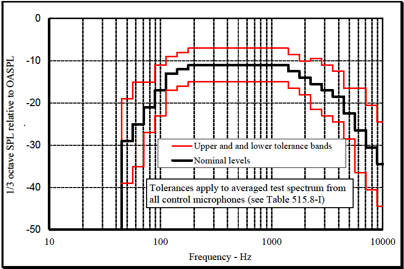
Figure description:
1/3 octave SPL relative to OASPL
Legend
- Upper and and lower tolerance bands — color: red; symbol: Solid line
- Nominal levels — color: black; symbol: Thick solid line
Annotations
- Tolerances apply to averaged test spectrum from all control microphones (see Table 515.8-I (text_label - position: Centered in the lower part of the plot area))
| Frequency (Hz) | Nominal Level (dB) | Upper Tolerance (dB) | Lower Tolerance (dB) |
|---|---|---|---|
| 50 | -29.0 | -19.0 | -39.0 |
| 63 | -25.0 | -15.0 | -35.0 |
| 80 | -21.0 | -11.0 | -27.0 |
| 100 | -17.0 | -11.0 | -23.0 |
| 125 | -13.0 | -8.0 | -17.0 |
| 160 | -12.0 | -8.0 | -16.0 |
| 200 | -11.0 | -7.0 | -15.0 |
| 250 | -11.0 | -7.0 | -15.0 |
| 315 | -11.0 | -7.0 | -15.0 |
| 400 | -11.0 | -7.0 | -15.0 |
| 500 | -11.0 | -7.0 | -15.0 |
| 630 | -11.0 | -7.0 | -15.0 |
| 800 | -11.0 | -7.0 | -15.0 |
| 1000 | -11.0 | -7.0 | -15.0 |
| 1250 | -11.0 | -7.0 | -15.0 |
| 1600 | -12.5 | -8.5 | -16.5 |
| 2000 | -14.0 | -10.0 | -18.0 |
| 2500 | -15.5 | -9.5 | -21.5 |
| 3150 | -17.0 | -11.0 | -23.0 |
| 4000 | -18.5 | -12.5 | -24.5 |
| 5000 | -22.5 | -16.5 | -28.5 |
| 6300 | -26.5 | -16.5 | -36.5 |
| 8000 | -30.5 | -20.5 | -40.5 |
| 10000 | -34.5 | -24.5 | -44.5 |
Notes: The frequency axis is logarithmic and uses standard 1/3 octave band center frequencies. Levels are relative to the Overall Sound Pressure Level (OASPL in decibels (dB.))
Figure 515.8A-1. Applied test spectrum.
| 1/3 octave center frequency Hz | Upper tolerance limit dB | Nominal level dB | Lower tolerance limit dB | 1/3 octave center frequency Hz | Upper tolerance limit dB | Nominal level dB | Lower tolerance limit dB |
|---|---|---|---|---|---|---|---|
| 50 | -19 | -29 | -39 | 800 | -7 | -11 | -15 |
| 63 | -15 | -25 | -35 | 1000 | -7 | -11 | -15 |
| 80 | -15 | -21 | -27 | 1250 | -7 | -11 | -15 |
| 100 | -11 | -17 | -23 | 1600 | -8.5 | -12.5 | -16.5 |
| 125 | -9 | -13 | -17 | 2000 | -10 | -14 | -18 |
| 160 | -8 | -12 | -16 | 2500 | -9.5 | -15.5 | -21.5 |
| 200 | -7 | -11 | -15 | 3150 | -11 | -17 | -23 |
| 250 | -7 | -11 | -15 | 4000 | -12.5 | -18.5 | -24.5 |
| 315 | -7 | -11 | -15 | 5000 | -16.5 | -22.5 | -28.5 |
| 400 | -7 | -11 | -15 | 6300 | -16.5 | -26.5 | -36.5 |
| 500 | -7 | -11 | -15 | 8000 | -20.5 | -30.5 | -40.5 |
| 630 | -7 | -11 | -15 | 10000 | -24.5 | -34.5 | -44.5 |
MIL-STD-810H METHOD
1.3 Limitations
Technical limitations restrict production and control of laboratory acoustic environments. Therefore, laboratory acoustic fields can be significantly different from many of the real fluctuating pressure loadings classed as "acoustic". Consider these limitations when choosing a test type and test facility, as well as in interpreting test results. For example, diffuse field acoustic noise (see paragraph 2.3.3.1) better represents acoustics in internal cavities where local reflection and re-radiation from vibrating structures predominate. For external skins exposed to aerodynamic turbulence or jet noise, grazing incidence acoustic noise (see paragraph 2.3.3.2) more closely represents flow/acoustic wave propagation along skin surfaces.
515.8-1.3 Simulation of Aerodynamic Turbulence
Where a broadband noise test is required for the simulation of aerodynamic turbulence, derive the test levels and durations in conjunction with those for the complementary mechanical test.