514.8-1 SCOPE
514.8-1 SCOPE
514.8-1 SCOPE
514.8-1 SCOPE
514.8-1 SCOPE
514.8-1 GENERAL
The purpose of this annex is to present considerations and techniques for developing Laboratory Vibration Test Schedules (LVTS) that can be utilized to simulate field vibration environments on a vibration table. Laboratory vibration tests are used extensively in lieu of more time-consuming and less cost effective field exposure tests. This annex specifically addresses vibration testing controlled to frequency-domain vibration spectra and is currently limited to single mechanical degree-of-freedom scenarios.
Analysis considerations and techniques depend somewhat on the intended use of the LVTS. An LVTS developed solely for functional testing will differ from one developed to induce a full lifetime of vibration exposure. This annex primarily addresses development for the purpose of inducing a lifetime of vibration exposure, but also discusses development for other purposes.
The primary function of Vibration Schedule Development (VSD) is to combine vibration measurements of numerous events that collectively represent an item’s lifetime vibration exposure into a manageable set of LVTS representing the equivalent exposure. The most dynamically accurate method to reproduce the full exposure would be to sequentially vibrate the system to all the individual, uncompressed events representing its full lifecycle. However, such an approach is generally not feasible from both schedule and economic perspectives and some compromises must be made to realize the benefits of testing in the laboratory. Time compression techniques based on fatigue equivalency are typically employed such that vibration testing can be performed in a timely and economic manner. This annex presents guidance for developing accurate representations, and issues that should be considered during the VSD process.
There is no single “best method” for VSD. Several methods have evolved at different organizations. Those methods were influenced by project specific issues, the nature of the vibration exposures, and the concerns of the given organization. This annex presents one VSD method plus two methods of combining spectra which can be useful for validation of test schedules, comparing one test schedule with another and comparing one test schedule with measured data. Critical issues are also presented that should be addressed by all methods to ensure accurate representations. Which methods are adopted may depend on the item being tested, the exposure to be replicated, the concerns of the parties involved, or other project specific factors. Ultimately, the VSD method selected must yield a set of vibration definitions and durations that collectively replicates the actual field exposure and/or induces the equivalent fatigue.
This annex addresses vibration issues only and does not address fatigue or damage potential of shock events. Shock concerns and respective test development issues are discussed in Method 516.8. Note that conditions that produce vibration may also produce shock (a pothole during road transport). Shock events should be identified, removed and addressed separately for analysis and testing.
514.8-1 INTRODUCTION
VSD requires full characterization of system vibration exposure. The characterization typically includes a collection of vibration time histories of all relevant exposure conditions, and a table of exposure times for those conditions. This Appendix presents general information relative to the acquisition and preparation of the time histories, and the generation of the exposure time table (system scenario).
514.8-1 COMBINING SPECTRA
This Appendix provides basic definitions and purely statistical approaches for combining spectra. The techniques discussed in this Appendix, combined with addressing mission scenarios and fatigue equivalence, formulate the basis for the VSD techniques that are discussed in Annex F, Appendices C and D.
After the scenario is selected and representative data are acquired, it is usually necessary to combine appropriate data into a single descriptor of the environment. For Single-Degree-of-Freedom (SDOF) vibration testing, this descriptor is generally the auto spectral density (ASD) function, a frequency based representation of the measured vibration amplitudes. Multiple-Degree-of-Freedom (MDOF) vibration testing will also require knowledge of the Cross Spectral Density (CSD) properties of motion. Although basic CSD definitions will be discussed, the MDOF VSD case will not be addressed in this Appendix. For further discussion of MDOF techniques refer to Method 527.2.
514.8-1 FATIGUE DAMAGE SPECTRUM METHOD OF COMBINING SPECTRA
In 1995, Henderson and Piersol introduced the concept of the fatigue damage spectrum to compare the potential damage to a test item exposed to different tests that had approximately a normal amplitude distribution (reference f). The fatigue damage spectrum is a spectral representation of a fatigue damage index as a function of any system's natural frequency. This spectrum is computed directly from the auto spectral density (ASD) function representing a test situation or a field environment, and provides a relative fatigue damage estimate based on acceleration level and exposure time. As opposed to the pure statistical techniques discussed in Appendix B, consideration of the exposure time as well as spectral and fatigue characteristics makes the FDS an attractive technique in development of a LVTS.
The fatigue damage spectrum is computed from:
C.1
where:
| DP(fn) | Damage index as a function of system natural frequency |
| fn | System natural frequency (variable), Hz |
| T | Exposure time in environment, seconds |
| G(fn) | ASD for a given environment, g²/Hz |
| ζ | Damping ratio of system at dominant natural frequency expressed as a decimal |
| b | Fatigue curve slope value when computed as a linear fit in a log-log domain. |
As discussed in Annex F, paragraph 9.2.1.2, the parameter employed in Equation (9.1) is not equal to . The value of is strongly influenced by the material S-N curve, but fatigue life is also influenced by the surface finish, the treatment, the effect of mean stress correction, the contributions of elastic and plastic strain, the waveshape of the strain time history, etc. Historically, a value of has been used for random environments, but values between 5 and 8 are commonly used (note the exponent is in Equation 9.5 when addressing ASD values). One may consider a similar substitution of for when using Equation C.1.
Since fatigue damage is based on a cumulative effect of various environments or conditions, a cumulative fatigue damage index can be calculated as the sum of the fatigue damage spectra for individual environments. Thus,
C.2
| where: | |
|---|---|
| DPt(fn) | = Total damage index spectrum. |
| DPi(fn) | = Individual environment damage spectra as defined in equation C.1. |
MIL-STD-810H
METHOD 514.8, ANNEX F, APPENDIX C
514.8-1 INTRODUCTION
This Appendix outlines a Vibration Schedule Development (VSD) procedure designed to combine an ensemble of vibration events and associated exposure times into a smaller set of vibration profiles and associated run times. The vibration events are in the form of a set of digital data files that collectively represent the full fatigue exposure of the test item. The goal is to produce a small set of Laboratory Vibration Test Schedules (LVTS) that can induce equivalent fatigue exposure with a vibration exciter. The procedure can be used to develop broadband random, Sine-on-Random (SOR) or Narrowband Random on Random (NBROR) LVTS. Figure 514.8F-D.1 illustrates the VSD procedure in an abbreviated block diagram format.
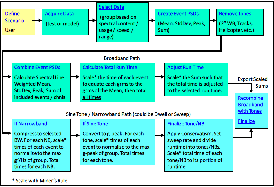
Figure description:
Vibration Schedule Development (VSD Flowchart Key Entities & Steps:
-
Initial Process Phase:
- Define Scenario: User-defined parameters.
- Acquire Data: Test or model-based acquisition.
- Select Data: Grouping by spectral content, usage, speed, or range.
- Create Event PSDs: Calculating Mean, StdDev, Peak, and Sum.
- Remove Tones: Filtering out 2” WB, Tracks, Helicopter, etc.
-
Broadband Path:
- Combine Event PSDs: Calculate spectral line weighted mean, StdDev, peak, and sum.
- Calculate Total Run Time: Scale event times using Miner’s Rule to equate to the mean ; total all times.
- Adjust Run Time: Scale the sum to adjust total time to the selected run time.
-
Sine Tone / Narrowband Path (Dwell or Sweep:
- If Narrowband: Compress to BW; scale times to normalize to max .
- If Sine Tone: Convert to g-peak; scale times to normalize to max g-peak.
- Finalize Tone/NB: Apply conservatism; set sweep rate; divide and scale runtime.
-
Final Output:
- Recombine Broadband with Tones: Finalize and export scaled sums.
Note: All scaling operations (* utilize Miner’s Rule.
Figure 514.8F-D.1. VSD flowchart.
Data are typically processed in multiple channel sets, as it is often desirable that specific channels are processed with common frequency resolution or be reduced to common test times to allow development of schedules based on multiple locations. The procedure is best implemented in specially designed software. Software tools should be developed to implement the following:
- a. A general-purpose signal analysis package used as a pre-processing tool prior to the actual schedule development. Routine pre-processing analyses includes: Time Histories, RMS vs. Time, Min/Max, Kurtosis, Histograms, Skewness and Stationarity.
- b. Specialized routines to manage the test database and manipulate the test data as necessitated by the VSD procedure. The routines can be grouped into a single software package for ease of implementation. The package should manipulate the event files and output an intermediate LVTS in ASCII or spreadsheet format.
MIL-STD-810H
- c. Spreadsheets developed to produce final LVTS’s using files generated by the specialized software. Spreadsheets provide a convenient method for addressing activities such as combining multiple channel profiles into a single LVTS, processing narrowband and/or sine tones, combining narrowband and broadband components, inclusion of fleet severity factors and scaling test times to user selected values.
- d. A subroutine to pick a series of breakpoints to represent the broadband profile generated by the process. The points should be picked such that the shape and rms level of the vibration profile are preserved with the minimal number of breakpoints.
The following definition is provided to aid in method discussion. A review of the definitions found in Annex F, paragraph 3 would also be beneficial.
Sum-Set – A matrix of ASDs used as an organizational tool for process implementation. There are two types of sum- set, the single-event ASD sum-set and the group sum-set. The two sum-sets will be defined as required in this Appendix.
Before the VSD process begins a number of parameters must be defined. Table 514.8F-D.I lists some parameters relevant for the process. Other parameters will be discussed in subsequent sections of this document as necessary.
The process can be implemented as discussed in the following sections.
| Block Size | The number of data samples to include in ASD calculation. The block size is typically set equal to the sample rate to give a 1 second block and 1 Hz ASD resolution. |
|---|---|
| Window Type | The window type to use for ASD calculation, typically Hann. |
| Minimum g-rms threshold | Used to assure low level events will not overly affect LVTS ASD shape. The threshold |
| is set as a g-rms ratio (default 50%) of the maximum ASD in the group. | |
| Crest Factor Threshold | These thresholds can be used to alert the analyst if a section of data is grossly non-Gaussian. The analyst can then decide if the data should be excluded from the development process. |
| Skewness Threshold | |
| Kurtosis Threshold | |
| Start Frequency | This is the start frequency for the broadband portion of the LVTS. This is typically set to 5 Hz or the frequency of the lowest tonal component. |
| End Frequency | This is the upper limit of the LVTS bandwidth. This should be set by a review of the data. Typically used values include 200 Hz, 500 Hz, or 2000 Hz. |
| Nₑ, Nₛ | Analyst defined factors defining the number of standard deviations to use in the process (default = 1). Nₑ is for an individual event and Nₛ is for combining multiple events. |
| Mₑ, Mₛ | Analyst defined factors to limit conservatism in the process. Mₑ is for an individual event and Mₛ is for combining multiple events. |
| DC Component | Remove the DC components from the time domain data before calculation of ASDs. The DC component is often a result of signal conditioner offset and can be removed without affecting LVTS development. |
514.8-1 INTRODUCTION
When a vibration excitation is applied to a mechanical system with one degree of freedom, the maximum value of the response of this system for a deterministic signal, or the probability of a maximum value for a random signal, can be calculated. This value is called the ‘maximum’ or the ‘extreme’ value. The maximum response spectrum is the curve that represents variations of the ‘maximum’ response value as a function of the natural frequency of the system with one degree of freedom, for a given damping factor ξ.
1.1 Purpose
The purpose of this Method is to provide guidance for defining vibration environments materiel may be exposed to throughout a life cycle and to provide guidance for the conduct of laboratory vibration tests. Vibration tests are performed to:
- a. Develop materiel to function in and withstand the vibration exposures of a life cycle including synergistic effects of other environmental factors, materiel duty cycle, and maintenance.
b. Verify that materiel will function in and withstand the vibration exposures of a life cycle.
514.8-1.1 Purpose
This Annex provides information intended to be useful in interpreting Method 514.8.
514.8-1.1 Purpose
This Annex provides guidance intended to be useful in determining the vibration levels and durations related to the manufacture and/or maintenance of materiel.
514.8-1.1 Purpose
This Annex provides information on transportation environments. It is intended to be useful in determining the vibration levels and durations of environmental life cycle events, and in defining the tests necessary to develop materiel to operate in and survive these environments.
514.8-1.1 Purpose
This Annex provides information intended to be useful in determining the vibration levels and durations of operational environmental life cycle events, and in defining the tests necessary to develop materiel to operate in and survive these environments.
514.8-1.1 Purpose
This Annex provides information intended to be useful in determining the vibration levels and durations of environmental life cycle events and in defining the tests necessary to develop materiel to operate in and survive these environments.
514.8-1.1 Auto and Cross Spectral Densities
Consider the following basic scalar definitions as presented by Bendat and Piersol (reference e). The discussions assume two stationary (ergodic) Gaussian random processes, {x(t)} and {y(t)}. The finite Fourier Transforms of {x(t)} a } and {y(t))} are defined as:
X (ƒ) = X(ƒ,T) = [ "*x(t) e−12mſt d Y(f) = Y(f,T) = ["˜y(t) e−1²st dt
The auto, Gxx (f), Gyy (f), and cross, Gxy (f), spectral densities of x(t)and y(t) for an “unlimited time” length T are defined respectively as:
1 Gxx (f) = = 2 lim =E[|X(ƒ,T)|²] T-00 T
1 Gyy (f) = = 2 lim E[|Y(F,T)|²] TT
1 Gxy (f) = 2 lim =E[X* (ƒ)Y(ƒ)]
Estimates of and as computed over a "finite time" interval are defined as:
=
MIL-STD-810H
METHOD 514.8, ANNEX F, APPENDIX B
and will have a discrete spectral resolution of B e ≈∆= f T 1 . There will generally be unacceptably large random error associated with this “raw” estimate. In practice the random error is reduced, by computing dn different averages of length T to obtain a “smooth” estimate defined as:
Ĝxx (f) = naT 2 {i=1\ nd [|X,(S,T)}] Ĝyy (ƒ) = naT 2 =Σi=11 nd B.1 Ĝxy (ƒ) ĜSS)=Σ[× (S)x, (S)] nT 2 nd
In practice, one will also have to consider the effects of overlapping and windowing options.
1.2 Application
-
a. General. Use this Method for all types of materiel except as noted in Part One, paragraph 1.3, and as stated in paragraph 1.3 below. For combined environment tests, conduct the test in accordance with the applicable test documentation. However, use this Method for determination of vibration test levels, durations, data reduction, and test procedure details.
-
b. Purpose of test. The test procedures and guidance herein are adaptable to various test purposes including development, reliability, qualification, etc. See Annex A for definitions and guidance.
-
c. Vibration life cycle. Table 514.8-I provides an overview of various life cycle situations during which some form of vibration may be encountered, along with the anticipated platform involved. Annex A provides definitions and engineering guidance useful in interpreting and applying this Method. Annexes B - E provide guidance for estimating vibration levels and durations and for selection of test procedures. Test Operations Procedure (TOP) 01-2-601 (paragraph 6.1, reference d), includes an assortment of specific ground vehicle data. TOP 01-2-603 (paragraph 6.1, reference xx) includes a few specific helicopter profiles and will be updated as more data become available.
-
d. Manufacturing. The manufacture and acceptance testing of materiel involves vibration exposures. These exposures are not directly addressed herein. It is assumed that materiel undergoes environmental testing during the manufacturing and acceptance process and this process produces the same environmental damage for any deliverable materiel. Thus the tests described in this Method are designed to verify the field life of the delivered materiel. When a change is made to the manufacturing process that involves increased vibration exposure, evaluate this increased vibration exposure to ensure the field life of subsequent materiel is not shortened. An example might be pre-production materiel completely assembled in one building, whereas production units are partially assembled at one site and then transported to another site for final assembly. Changes in the manufacturing vibration environment should be evaluated with regard to the need for design and (re)qualification. (See Annex B)
-
e. Environmental Stress Screening (ESS). Many materiel items are subjected to ESS, burn-in, or other production acceptance test procedures prior to delivery to the government, and sometimes during maintenance. As in basic production processes, it is assumed that both the test units and the field units receive the same vibration exposures, so that environmental test results are valid for the field units. Where units do not necessarily receive the same exposures, such as multiple passes through ESS, apply the maximum allowable exposures to the items used for environmental test as pre-conditioning for the environmental tests. (See Annex A, paragraph 2.1.6, and Annex B, paragraph 2.3.)
MIL-STD-810H
METHOD 514.8
| Life Phase | Platform | Category | Materiel Description | Annex | Test¹ |
|---|---|---|---|---|---|
| Manufacture / Maintenance | Plant Facility / Maintenance Facility | 1. Manufacture / Maintenance processes | Materiel / Assembly / Part | B | 2 |
| 2. Shipping, handling | 2 | ||||
| 3. ESS | 3 | ||||
| Transportation | Trucks and Trailers | 4. Secured Cargo | Materiel as secured cargo4 | C | I |
| 5. Loose Cargo | Materiel as loose cargo4 | II | |||
| 6. Large Assembly Transport | Large assemblies, shelters, van and trailer units4 | III | |||
| Aircraft | 7. Jet | Materiel as cargo | I | ||
| 8. Propeller | |||||
| 9. Helicopter | |||||
| Watercraft5 | 10. Marine Vehicles | ||||
| Railroad | 11. Train | ||||
| Operational | Aircraft | 12. Jet | Installed Materiel | D | I |
| 13. Propeller | |||||
| 14. Helicopter | |||||
| Aircraft Stores | 15. Jet | Assembled stores | IV | ||
| 16. Jet | Installed in stores | I | |||
| 17. Propeller | Assembled / Installed in stores | IV/I | |||
| 18. Helicopter | |||||
| Missiles | 19. Tactical Missiles | Assembled / installed in missiles (free flight) | |||
| Ground | 20. Ground Vehicles | Installed Materiel in wheeled /tracked trailer | I/III | ||
| Watercraft5 | 21. Marine Vehicles | Installed Materiel | I | ||
| Engines | 22. Turbine Engines | Materiel Installed on Engines | |||
| Personnel | 23. Personnel | Materiel carried by/on personnel | 2 | ||
| Supplemental | All | 24. Minimum Integrity | Installed on Isolators / Life cycle not defined | E | I |
| All Vehicles | 25. External Cantilevered | Antennae, airfoils, masts, etc. | 2 |
| 1 Test procedure - see paragraph 4. |
| 2 See Annexes B, C, D, & E, and the paragraphs related to categories identified in the "Category" column. It is highly recommended that users read Annex A before applying Annex B, C, D and E vibration schedules |
| 3 Refer to the applicable ESS procedure (for additional guidance see Annex A, Paragraph 2.1.6). |
| 4 See paragraph 2.3.2 below. |
| 5 For Navy vessels, see Method 528.1. |
MIL-STD-810H
METHOD 514.8
514.8-1.2 Application
The following discussions concern basic engineering information. They are intended as a quick introduction to the subject matter and are offered without detailed explanations, mathematics, or references. If further information or understanding is required, the technical literature and engineering textbooks should be consulted. Paragraph 6.1, reference aa, is recommended as a starting point.
514.8-1.2 Application
Recommended actual environments be measured, and materiel life cycle durations be used to develop materiel design and test criteria whenever possible. Existing databases can sometimes be used in lieu of measurements. A preliminary environmental life cycle based on data provided herein can be useful as a planning tool. A preliminary life cycle definition can be used to concentrate limited resources on those vibration exposures most significant to the materiel. Guidance for setting design and test exposure values is given below with descriptions of vibration environments of many typical life cycle events. Suggested alternate criteria (levels and durations) or other guidance are recommended for those cases where measured data defining the actual environments are not available.
514.8-1.2 Application
It is recommended that actual environments be measured and materiel life cycle durations be used to develop materiel design and test criteria whenever possible. Existing databases can sometimes be used in lieu of measurements. A preliminary environmental life cycle based on data provided herein can be useful as a planning tool. A preliminary life cycle definition can be used to concentrate limited resources on those vibration exposures most significant to the materiel. Guidance for setting design and test exposure values is given below with descriptions of vibration environments of many typical life cycle events. Suggested alternate criteria (levels and durations) or other guidance is recommended for those cases where measured data defining the actual environments are not available. Table 514.8-I in the front part of this Method contains an outline of the following paragraph with references to the paragraph numbers. For transportation vibration typical (default) missions are illustrated in Figure 514.8C-1.
514.8-1.2 Application
Recommend actual environments be measured and materiel life cycle durations be used to develop materiel design and test criteria whenever possible. Existing databases can sometimes be used in lieu of measurements. A preliminary environmental life cycle based on data provided herein can be useful as a planning tool. A preliminary life cycle definition can be used to concentrate limited resources on those vibration exposures most significant to the materiel. Guidance for setting design and test exposure values is given below with descriptions of vibration environments of many typical life cycle events. Suggested alternate criteria (levels and durations) or other guidance is recommended for those cases where measured data defining the actual environments are not available. Table 514.8-I in the front part of this Method contains an outline of the following paragraphs with references to the paragraph numbers.
514.8-1.2 Application
Recommend actual environments be measured and materiel life cycle durations be used to develop materiel design and test criteria whenever possible. Existing databases can sometimes be used in lieu of measurements. A preliminary environmental life cycle based on data provided herein can be useful as a planning tool. A preliminary life cycle definition can be used to concentrate limited resources on those vibration exposures most significant to the materiel. Guidance for setting design and test exposure values is given below with descriptions of vibration environments of many typical life cycle events. Suggested alternate criteria (levels and durations) or other guidance is recommended for those cases where measured data defining the actual environments are not available. Table 514.8-I in the front part of this Method contains an outline of the following paragraph with references to the paragraph numbers.
514.8-1.2 Confidence Interval of ASD Estimates
During the data collection phase of a VSD effort, every effort will be made to acquire a sufficiently long record of field data to ensure an accurate estimate of the ASD and CSD. In reality, it is not always possible to acquire sufficiently long time histories as to minimize error in the spectral estimates of interest. Given that the number of averages is not a constant for all measurements, one should track the error associated with spectral estimates as they are the basis for the VSD procedures that are the interest of this annex.
As shown in reference e, the sampling distribution for an ASD estimate may be written in terms of the Chi squared distribution as:
Ĝxx (ƒ) _ X = n = 2nd Gxx (f) n
Observe that the number of degrees of freedom n = 2 n d results from the fact that each instantaneous estimate of the complex number X ( ) f consists of statistically independent real and imaginary components.
Statistical confidence bands can be placed around this estimate of G (ƒ): as:
nĜ(f) nĜ(f) χα 2 x(ƒ) ≤. x² B.2 n n;1-
where: α defines the confidence interval (i.e., for a 90 percent confidence interval α =.1)
where: defines the confidence interval (i.e., for a percent confidence interval )
Observe that the confidence intervals are strictly related to the accuracy of estimate of and in no manner addresses the scatter within individual spectral bins of the individual averages used to compute .
MIL-STD-810H METHOD 514.8, ANNEX F, APPENDIX B
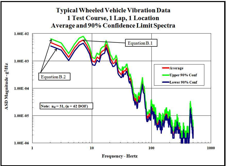
Figure description:
Typical Wheeled Vehicle Vibration Data 1 Test Course, 1 Lap, 1 Location Average and 90% Confidence Limit Spectra
Typical Wheeled Vehicle Vibration Data
Legend
- Average — color: red; symbol: Solid line
- Upper 90% Conf — color: green; symbol: Solid line
- Lower 90% Conf — color: blue; symbol: Solid line
Annotations
- Equation B.1 (text_label - position: Pointing to Upper 90% Conf at approx 2Hz and 7Hz peaks)
- Equation B.2 (text_label - position: Pointing to Average and Lower 90% Conf at approx 2Hz peak)
- Note: n_d = 31, (n = 62 DOF (text_label - position: x = 2, y = 2E-05))
| Frequency - Hertz | Average (g²/Hz) | Upper 90% Conf (g²/Hz) | Lower 90% Conf (g²/Hz) |
|---|---|---|---|
| 2.0 | 4.50E-03 | 6.50E-03 | 3.50E-03 |
| 3.0 | 3.00E-03 | 4.20E-03 | 2.30E-03 |
| 4.0 | 1.40E-03 | 1.90E-03 | 1.00E-03 |
| 7.0 | 6.00E-03 | 8.20E-03 | 4.40E-03 |
| 10.0 | 1.50E-03 | 2.20E-03 | 1.10E-03 |
| 12.0 | 9.00E-04 | 1.30E-03 | 7.00E-04 |
| 14.0 | 1.80E-03 | 2.50E-03 | 1.30E-03 |
| 17.0 | 4.00E-03 | 5.50E-03 | 3.00E-03 |
| 20.0 | 1.50E-03 | 2.20E-03 | 1.10E-03 |
| 25.0 | 8.50E-04 | 1.20E-03 | 6.20E-04 |
| 35.0 | 5.00E-04 | 7.50E-04 | 3.30E-04 |
| 45.0 | 4.00E-05 | 7.00E-05 | 2.20E-05 |
| 55.0 | 7.00E-05 | 1.10E-04 | 4.00E-05 |
| 70.0 | 1.50E-04 | 2.40E-04 | 8.50E-05 |
| 85.0 | 1.20E-05 | 2.20E-05 | 7.00E-06 |
| 100.0 | 1.40E-05 | 2.50E-05 | 8.00E-06 |
| 150.0 | 6.00E-06 | 1.20E-05 | 3.50E-06 |
| 180.0 | 1.10E-05 | 2.00E-05 | 6.00E-06 |
| 250.0 | 4.00E-06 | 8.00E-06 | 2.20E-06 |
| 400.0 | 1.80E-05 | 3.30E-05 | 1.10E-05 |
| 500.0 | 3.00E-06 | 6.00E-06 | 1.50E-06 |
Figure 514.8F-B.1. 90-percent confidence limits for nd = 31 linear spectral averages.
1.3 Limitations
- a. Safety testing. This Method may be used to apply specific safety test requirements as coordinated with the responsible safety organization. However, vibration levels or durations for specific safety related issues are not provided or discussed.
- b. Platform/materiel interaction. In this Method, vibration requirements are generally expressed as inputs to materiel that is considered to be a rigid body with respect to the vibration exciter (platform, shaker, etc.). While this is often not true, it is an acceptable simplification for smaller materiel items. This method does not attempt to address the validity of this assumption and leaves it to the user to determine proper treatment of a given materiel item/platform. The guidance below addresses typical platform/material interaction scenarios. Additional discussion of platform/materiel interaction is provided in Annex A, paragraph 2.4.
- (1) Where impedance mismatch between platform/materiel and laboratory vibration exciter/test item are significantly different, force control or acceleration limiting control strategies may be required to avoid unrealistically severe vibration response (see paragraph 4.2). The use of control limits should be based upon field data measurements and the sensitivity of the materiel to excessive vibratory loading (e.g., a resonance condition).
- (2) In certain cases in which the field measured response is well defined on a small component and the duration of the vibration is short, execution of the laboratory test under open loop waveform control based upon the field measured data is an option.
- (3) For large materiel items, it is necessary to recognize that the materiel and the exciter vibrate as a single flexible system and may be difficult to control as a laboratory vibration test. An example is a shelter transported to the field as a pre-assembled office, laboratory, etc. A suitable test for such systems would be the large assembly transport test (Procedure III) of paragraph 4.4.3.
- (4) Proper treatment of a given materiel item may vary throughout the life cycle. An example might be a galley designed for an aircraft. For the operational environment (installation on an operating aircraft), consider the galley structure as aircraft secondary structure, and design and test accordingly. Design subassemblies within the galley (e.g., coffee maker) for vibration levels based on guidance of Annex D, and tested in accordance with Procedure I. When packaged for shipment, the packaging, galley, and subassemblies are considered a single materiel item, and tested accordingly.
- c. Environmental Stress Screening (ESS). This Method does not contain guidance for selection of ESS exposures. Some discussion is in Annex A, paragraph 2.1.6, and Annex B, paragraph 2.3.
- d. Multiple Exciter Testing. This Method is limited to consideration of one mechanical degree-of-freedom based on a spectral reference. Refer to Method 527 for further guidance on multiple exciter testing, and Method 525 for time waveform replication.
- e. Synergistic Effects. Combine the guidance of this Method with the guidance of Part One and other methods herein to account for environmental synergism.
514.8-1.3 Limitations
See paragraph 1.3 in the front part of this Method.
514.8-1.3 Limitations
See paragraph 1.3 in the front part of this Method.
514.8-1.3 Limitations
See paragraph 1.3 in the front part of this Method.
514.8-1.3 Limitations
See paragraph 1.3 in the front part of this Method.
514.8-1.3 Limitations
See paragraph 1.3 in the front part of this Method, as well as paragraph 2.1.1a(1) below.