517.3-4 ACCELEROMETER DATA WITH BASE STRAIN EFFECTS
Although piezoresistive (PR) accelerometers are recommended for pyroshock measurement, these accelerometers will quite often respond to the initial compressive wave from the pyroshock with a base strain response. The base strain will create an additional velocity change in the acceleration time history. Although the strain pulse is generally not detectable in the acceleration time history, the velocity change will be evident in the integral of the acceleration.
The base strain induced into the case of a PR accelerometer during installation may be relieved with hammer taps during the initial steps in the Procedure.
Example acceleration time histories are in Figure 517.3A-12 and Figure 517.3A-14; the corresponding velocity time histories obtained by integrating the acceleration are shown in Figure 517.3A-13 and Figure 517.3A-15.
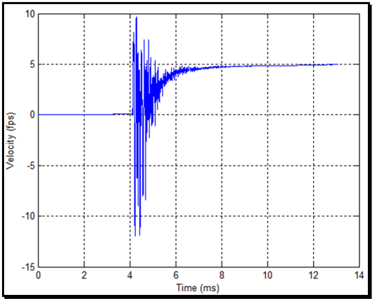
Figure description:
| Time (ms) | Velocity (fps) |
|---|---|
| 0.0 | 0.0 |
| 1.0 | 0.0 |
| 2.0 | 0.0 |
| 3.0 | 0.0 |
| 3.5 | 0.0 |
| 3.8 | 0.1 |
| 4.0 | 0.0 |
| 4.1 | 8.2 |
| 4.2 | -12.0 |
| 4.3 | 9.6 |
| 4.4 | -11.8 |
| 4.5 | 6.5 |
| 4.6 | -8.4 |
| 4.7 | 7.4 |
| 4.8 | -4.8 |
| 5.0 | 5.4 |
| 5.2 | 1.2 |
| 5.4 | 4.9 |
| 5.6 | 3.2 |
| 5.8 | 4.5 |
| 6.0 | 4.0 |
| 6.5 | 4.6 |
| 7.0 | 4.7 |
| 8.0 | 4.8 |
| 9.0 | 4.9 |
| 10.0 | 4.9 |
| 11.0 | 4.95 |
| 12.0 | 5.0 |
| 13.0 | 5.0 |
Notes: The chart shows a high-frequency oscillatory event starting at approximately 4 ms, which rapidly damps out by 8 ms and stabilizes at a velocity of 5 fps.
Figure 517.3A-13. The integral of the acceleration data in Figure 517.3A-12.
MIL-STD-810H METHOD 517.3 ANNEX A
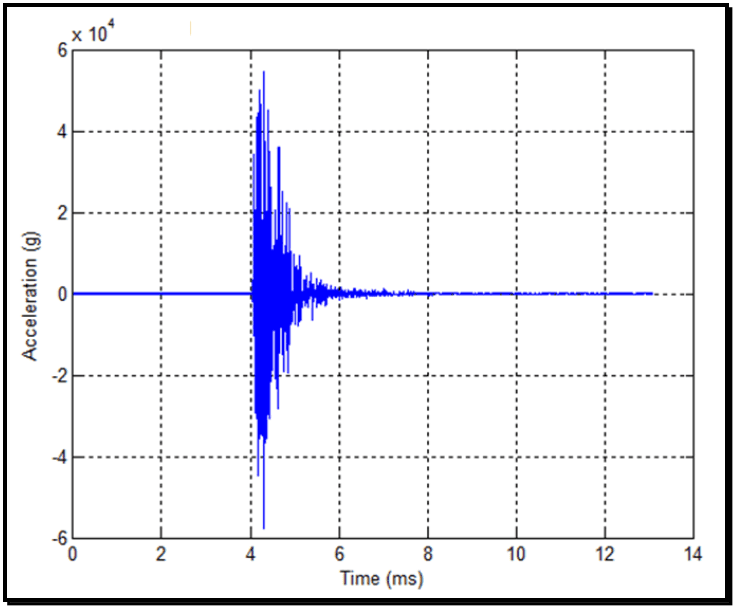
Figure description:
| Time (ms) | Acceleration (g) |
|---|---|
| 0.0 | 0 |
| 1.0 | 0 |
| 2.0 | 0 |
| 3.0 | 0 |
| 3.9 | 0 |
| 4.0 | 5000 |
| 4.1 | -35000 |
| 4.2 | 48000 |
| 4.3 | 55000 |
| 4.35 | -58000 |
| 4.4 | 45000 |
| 4.5 | -30000 |
| 4.7 | 25000 |
| 4.9 | -15000 |
| 5.0 | 10000 |
| 5.5 | 5000 |
| 6.0 | 2500 |
| 7.0 | 1000 |
| 8.0 | 500 |
| 9.0 | 200 |
| 10.0 | 0 |
| 11.0 | 0 |
| 12.0 | 0 |
| 13.0 | 0 |
Notes: The chart displays a high-frequency, decaying acceleration pulse starting at approximately 4.0 ms. The vertical axis is scaled by 10^4 g.
Figure 517.3A-14. A near-field pyroshock acceleration time history.
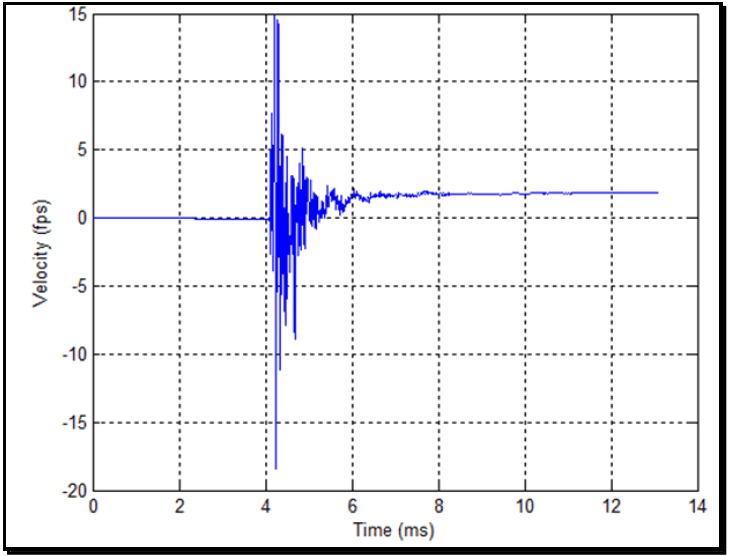
Figure description:
Velocity vs Time
| Time (ms) | Velocity (fps) |
|---|---|
| 0.0 | 0.00 |
| 1.0 | 0.00 |
| 2.0 | 0.00 |
| 3.0 | 0.00 |
| 3.8 | 0.00 |
| 3.9 | -0.20 |
| 4.0 | 0.00 |
| 4.1 | 7.50 |
| 4.15 | 14.90 |
| 4.2 | -18.50 |
| 4.25 | -5.00 |
| 4.3 | 4.00 |
| 4.4 | -11.00 |
| 4.5 | 5.00 |
| 4.6 | -2.00 |
| 4.7 | -8.70 |
| 4.8 | 3.00 |
| 4.9 | 4.50 |
| 5.0 | 1.00 |
| 5.1 | -1.50 |
| 5.2 | 2.50 |
| 5.4 | 2.20 |
| 5.6 | 0.50 |
| 5.8 | 2.10 |
| 6.0 | 1.30 |
| 6.5 | 1.80 |
| 7.0 | 1.60 |
| 8.0 | 1.80 |
| 9.0 | 1.70 |
| 10.0 | 1.80 |
| 11.0 | 1.80 |
| 12.0 | 1.80 |
| 13.0 | 1.80 |
Notes: The chart shows a rapid oscillation in velocity starting at approximately 4 ms, following a period of near-zero velocity. The oscillations gradually dampen and settle to a steady state velocity of approximately 1.8 fps after 6 ms.
Figure 517.3A-15. The integral of the acceleration data in Figure 517.3A-14.
MIL-STD-810H METHOD
4.1 Test Facility
Pyroshock can be applied using actual pyrotechnic devices in the design configuration or in a simulated configuration, conventional high acceleration amplitude/frequency test input devices or, under certain restricted circumstances, an electrodynamic shaker. The pyroshock apparatus may incorporate a compressed gas shock tube, metal-on-metal contact, ordnance-generated pyroshock simulator, actual pyrotechnic device on a scale model, actual pyrotechnic device on a full scale model, or other activating types. For Procedure I or Procedure II, references related to ordnance devices must be consulted. For Procedures III and IV, paragraph 6.1, reference b, provides a source of alternative test input devices, their advantages and limitations. In Procedure III it is assumed that all parts of the materiel lie in the mid-field of the pyrotechnic device. Consult paragraph 6.1, reference b, for guidelines and consideration for such testing. For Procedures IV and V, it is assumed that all parts of the materiel lie in the far-field of the pyrotechnic device and the measured or predicted data are consistent with the 3000 Hz frequency definition of the far-field as well
as the limitations of the electrodynamic shaker in addition to the acceleration amplitude limitations. For large materiel, the velocity input of the shaker may exceed the velocity of the materiel under the actual pyroshock environment. For velocity sensitive materiel, this may constitute an overtest. In the ensuing paragraphs, the portion of the test facility responsible for delivering the pyroshock to the materiel will be termed the “shock apparatus.” Such shock apparatus includes the pyrotechnic shock device and the fixturing configuration in Procedures I and II, the mechanical exciter and the fixturing configuration in Procedure III, and the mechanical exciter and electrodynamic shaker and the fixturing configuration in Procedures IV and V.
4.2 Controls
4.2.1 Calibration
Ensure the shock apparatus is calibrated for conformance with the specified test requirement from the selected procedure. For Procedure I, there is no pre-shock calibration other than ensuring the configuration is in accordance with the test plan. For Procedure II, before the test item is attached to the resonating plate, it is necessary to attach a calibration load, and obtain measured data under test conditions to be compared with the desired test response. Exercise caution so that the pre-test shocks do not degrade the resonating plate configuration. Calibration is crucial for Procedures III and IV. Before the test item is attached to the shock apparatus, it is necessary to attach a calibration load and obtain measured data under test conditions to be compared with the desired test response. For Procedure V, using the SRS method with proper constraints on the effective duration of the transient, calibration is necessary. Before the test item is attached to the shock apparatus, attach a calibration load, and obtain measured data under test conditions to be compared with the desired test response. Additional tolerances and calibration procedures are provided in Part One, paragraphs 5.2 and 5.3.2, respectively.
4.2.2 Tolerances
The following are guidelines for test tolerances for pyroshock for the five Procedures. All tolerances are specified on the maximax acceleration SRS. Any tolerances specified on the pseudo-velocity SRS must be derived from the tolerances on the maximax acceleration SRS, and be consistent with those tolerances. For an array of measurements defined in terms of a "zone" (paragraph 6.1, reference e), a tolerance may be specified in terms of an average of the measurements within a "zone." However, this is, in effect, a relaxation of the single measurement tolerance, and that individual measurements may be substantially out of tolerance while the average is within tolerance. In general, when specifying test tolerances based on averaging for more than two measurements within a zone, the tolerance band should not exceed the 95/50 one-sided normal tolerance upper limit computed for the logarithmically transformed SRS estimates, or be less than the mean minus 1.5dB. Any use of "zone" tolerances and averaging must have support documentation prepared by a trained analyst. Additional tolerances and calibration procedures are provided in Part One, paragraphs 5.2 and 5.3.2, respectively.
4.2.2.1 Procedure I - Near-field with an Actual Configuration and Procedure II - Near-field with a Simulated Configuration
If prior measured data are available, or a series of pyroshocks are performed, all acceleration maximax SRS shall be computed at the center frequency of one-twelfth octave bands. The individual SRS values (points) are to be within - 3 dB to + 6 dB for a minimum of 80 percent of the SRS values in the bandwidth from 100 Hz to 20 kHz. For the remaining 20 percent of the SRS values in the frequency band, the individual SRS values are to be from - 6 dB to + 9 dB. Ensure at least 50 percent of the individual SRS values exceed the nominal test specification.
4.2.2.2 Procedure III- Mid-field with a Mechanical Test Device
If prior measured data are available, or a series of pyroshocks are performed, all acceleration maximax SRS shall be computed at the center frequency of one-twelfth octave bands. The individual SRS values (points) are to be within - 3 dB to + 6 dB for a minimum of 90 percent of the SRS values in the bandwidth from 100 Hz to 20 kHz. For the remaining 10 percent of the SRS values in the frequency band, the individual SRS values are to be from - 6 dB to + 9 dB. Ensure at least 50 percent of the individual SRS values exceed the nominal test specification.
MIL-STD-810H
METHOD 517.3
4.2.2.3 Procedure IV - Far-field with a Mechanical Test Device
If prior measured data are available, or a series of pyroshocks are performed, all acceleration maximax SRS shall be computed at the center frequency of one-twelfth octave bands. The individual SRS values (points) are to be within - 3 dB to + 6 dB for a minimum of 90 percent of the SRS values in the bandwidth from 100 Hz to 20 kHz. For the remaining 10 percent of the SRS values in the frequency band, the individual SRS values are to be from - 6 dB to + 9 dB. Ensure at least 50 percent of the individual SRS values exceed the nominal test specification.
4.2.2.4 Procedure V - Far-field with an Electrodynamic Shaker
If prior measured data are available, or a series of pyroshocks are performed, all acceleration maximax SRS shall be computed at the center frequency of one-twelfth octave bands. The individual SRS values (points) are to be within - 1.5 dB to +3 dB for a minimum of 90 percent of the SRS values in the bandwidth from 10 Hz to 3 kHz. For the remaining 10 percent of the SRS values in the frequency band, the individual SRS values are to be from - 3 dB to + 6 dB. Ensure at least 50 percent of the individual SRS values exceed the nominal test specification.
4.2.3 Instrumentation
In general, acceleration will be the quantity measured to meet a specification, with care taken to ensure acceleration measurements can be made that provide meaningful data (paragraph 6.1, references b and d). For pyroshock measurements in and close to the near-field, loss of measurement system integrity is not unusual. On occasion, more sophisticated devices may be employed, e.g., laser Doppler vibrometer. In these cases, give special consideration to the measurement instrument amplitude and frequency range specifications in order to satisfy the calibration, measurement and analysis requirements. With regard to measurement technology, accelerometers, strain gages and laser Doppler vibrometers are commonly used devices for measurement. In processing pyroshock data, it is important to be able to detect anomalies. For example, it is well documented that accelerometers may offset or zeroshift during mechanical shock, pyroshock, and ballistic shock (paragraph 6.1, references a, b, t andu). Additional discussion on this topic is found in the ballistic shock method. A part of this detection is the integration of the acceleration amplitude time history to determine if it has the characteristics of a high frequency velocity trace. In addition, instrumentation to measure test item function may be required. In this case, obtain suitable calibration standards and adhere to them. Transducer performance continues to improve with time, however, inventories across all laboratories may not be of the latest generation, and thereby making detailed calibrations critical in understanding individual transducer performance.
- a. Accelerometers. Ensure the following:
- (1) Amplitude Linearity: It is desired to have amplitude linearity within 10 percent over the entire operating range of the device. Since accelerometers (mechanically isolated or not) may also show zeroshift (paragraph 6.1, references a, b, t and u), there is risk in not characterizing these devices over their entire amplitude range. To address these possible zeroshifts, high pass filtering (or other data correction technique) may be required. Such additional post-test correction techniques increase the risk of distorting the measured pyroshock environment. Consider the following in transducer selection:
(a) It is recognized that accelerometers may have both non-linear amplification and non-linear frequency content below 10,000 Hz (paragraph 6.1, references a, b, t and u). In order to understand the non-linear amplification and frequency characteristics, it is recommended that shock linearity evaluations be conducted at intervals of 20 to 30 percent of the rated amplitude range (inclusive of the maximum rated range) of the accelerometer to identify the actual amplitude and frequency linearity characteristics and useable amplitude and frequency range. Additionally, the shock pulse duration for the evaluations is calculated as:
Where is the duration (baseline) of the acceleration pulse and is the maximum specified frequency range for the accelerometer. For Near-field pyroshock is 100,000 Hz. For Mid-field and
Far-field pyroshock is 10,000 Hz. If Hopkinson bar testing is used for these evaluations then care must be taken to make sure that a non-dispersive pulse duration is used (paragraph 6.1, reference 5). In absence of techniques for addressing 100,000 Hz characterizations and considering durations limitations associated with non-dispersive reference requirements, a Hopkinson bar (0.75 inch diameter) may be used with a 20 microsecond reference pulse duration, . The roll-off in frequency response of this greater than nominal duration reference must be considered in evaluating linearity. The requirements for shock amplitude and duration are subject to the usual shock tolerance requirements of . In addition, it is recognized that the lower limit for Hopkinson bar testing is usually 5,000 g. Therefore, in order to span the full accelerometer range as defined above, it may be necessary to use more than one calibration apparatus, i.e. a drop ball calibrator as well as a Hopkinson bar.
(b) For cases in which response below 2 Hz is desired, a piezoresistive accelerometer measurement is required.
- (2) Frequency Response: A flat response within ± 5 percent across the frequency range of interest is required. Since it is generally not practical or cost effective to conduct a series of varying pulse width shock tests to characterize frequency response, a vibration calibration is typically employed. For the case of a high range accelerometer (200,000 g) with low output, there may be SNR issues associated with a low level vibration calibration. In such cases a degree of engineering judgment will be required in the evaluation of frequency response with a revised requirement for flat frequency response to be within ± 1 dB across the frequency range of interest.
- (3) Accelerometer Sensitivity: The sensitivity of a shock accelerometer is expected to have some variance over its large amplitude dynamic range.
(a) If the sensitivity is based upon the low amplitude vibration calibration, it is critical that the linearity characteristics of the shock based “Amplitude Linearity” be understood such that an amplitude measurement uncertainty is clearly defined.
(b) Ideally, vibration calibration and shock amplitude linearity results should agree within 10 percent over the amplitude range of interest for a given test.
-
(4) Transverse sensitivity should be less than or equal to 7 percent.
-
(5) The measurement device and its mounting will be compatible with the requirements and guidelines provided in paragraph 6.1, reference a.
-
(6) Unless it is clearly demonstrated that a piezoelectric accelerometer (mechanically isolated or not) can meet the pyroshock requirements and is designed for oscillatory shock (not one-sided shock pulses), recommend piezoresistive accelerometers be used for high intensity, near-field pyroshock events. Piezoresistive or piezoelectric accelerometers may be used in scenarios in which levels are known to be within the established (verified through calibration) operating range of the transducer (mid-field and far-field), thereby avoiding non-linear amplification and frequency content.
-
b. Other Measurement Devices. Ensure any other measurement devices used to collect data are demonstrated to be consistent with the requirements of the test, in particular, the calibration and tolerance information provided in paragraph 4.2.
-
c. Signal conditioning. Use signal conditioning compatible with the instrumentation requirements on the materiel. In particular, filtering will be consistent with the response time history and frequency content requirements. Use signal conditioning compatible with the requirements and guidelines provided in paragraph 6.1, references b and d. In particular, use extreme care in filtering the acceleration signals either (1) directly at the attachment point, i.e., mechanical filtering to reduce the very high frequencies associated with the pyroshock, or (2) at the amplifier output. Never filter the signal into the amplifier for fear of filtering bad measurement data, and the inability to detect the bad measurement data at the amplifier output. The signal from the signal conditioning or recording device must be anti-alias filtered before digitizing with an analog, linear phase shift filter over the frequency range of interest. Use an analog anti-alias filter configuration, other signal conditioning, and the data acquisition system that:
-
(1) Meets aliasing requirements in Figure 517.3-7.
-
(2) Has phase linearity to within +/- 5° in the data passband.
-
(3) Has a passband uniform to within one dB across the frequency band of interest.
-
(4) Has unit step response with less than 10% (1 dB) overshoot.
-
d. Additional Pyroshock Requirements. Additional requirements are necessary for pyroshock measurement, especially near-field and mid-field pyroshock. The requirements of Paragraph 2.3.2 of this document must be used to prevent aliasing contamination of the data. Slew rate specifications are also important because slew rate contamination can alter the low frequency content of the data, and become part of an erroneous specification as per Appendix A of this document. To prevent distortion caused by spurious electrical noise, the data recording instrumentation shall be capable of recording a signal of one half full scale voltage in 1 microsecond without slew rate distortion. For example, if a system is capable of ± 10 volts full scale = 20 volt peak-to-peak, then a slew rate of 10 volt/microsecond is required. Exceptions to these criteria shall be documented and sufficiently justified to prove that aliasing and other contamination of the data has not occurred.
4.2.4 Data Analysis
- a. Analyze pyroshock data for the extended bandwidth of 10 Hz to 100,000 kHz to examine the low frequencies for data contamination, and to ensure the high frequency content has been captured.
- b. For digital filters used to meet the previous requirement, use a filter with linear phase-shift characteristics and a pass band flatness within one dB across the frequency range specified for the accelerometer (see paragraph 4.2.3).
- c. Ensure the analysis procedures are in accordance with those requirements and guidelines provided in paragraph 6.1, references b and d. In particular, validate the pyroshock acceleration amplitude time histories according to the procedures in paragraph 6.1, reference d. Integrate each amplitude time history to detect any anomalies in the measurement system, e.g., cable breakage, slew rate of amplifier exceeded, data clipped, unexplained accelerometer offset, etc. Compare the integrated amplitude time histories against criteria given in paragraph 6.1, references b and d, and Annex A of this Method. For all Procedures to detect emission from extraneous sources, e.g., EMI, configure an accelerometer as a noise gage (without acceleration sensing element or just another accelerometer that is not attached to the unit under test) and process its response in the same manner as for the other accelerometer measurements. If this noise gage exhibits any characteristic other than very low level noise, consider the acceleration measurements to be contaminated by an unknown noise source in accordance with the guidance in paragraph 6.1, references b and d.
4.3 Test Interruption
Test interruptions can result from two or more situations, one being from failure or malfunction of test equipment. The second type of test interruption results from failure or malfunction of the test item itself during operational checks.
4.3.1 Interruption Due To Laboratory Equipment Malfunction
- a. If the test excitation fails to function, refer to local SOPs.
- b. Generally, if the pyroshock device malfunctions or interruption occurs during a mechanical shock pulse, repeat that shock pulse. Care must be taken to ensure stresses induced by the interrupted shock pulse do not invalidate subsequent test results. Inspect the overall integrity of the materiel to ensure pre-shock test materiel structural and functional integrity. Record and analyze data from such interruptions before continuing with the test sequence.
4.3.2 Interruption Due To Test Item Operation Failure
Failure of the test item(s) to function as required during operational checks presents a situation with two possible options. These decisions are made on a case by case basis, with test item cost and schedule considerations, as well as overall materiel cost and schedule requirements.
- a. The preferable option is to replace the test item with a “new” one and restart from Step 1.
- b. A second option is to replace / repair the failed or non-functioning component or assembly with one that functions as intended, and restart the entire test from Step 1.
MIL-STD-810H
METHOD 517.3
NOTE: When evaluating failure interruptions, consider prior testing on the same test item and consequences of such.
4.4 Test Execution
4.4.1 Preparation for Test
4.4.1.1 Preliminary Steps
Prior to initiating any testing, review pretest information in the test plan to determine test details (e.g., procedures, test item configuration, pyroshock levels, number of pyroshocks):
- a. Choose the appropriate test Procedure.
- b. Determine the appropriate pyroshock levels for the test prior to calibration for Procedures II through V from previously processed data if available, otherwise use the calibration levels.
- c. Ensure the pyroshock signal conditioning and recording devices have adequate amplitude range and frequency bandwidth as per paragraph 4.2.3. It may be difficult to estimate a peak signal and, therefore, the amplitude range for the instrumentation. In general, there is no data recovery from a clipped signal. However, for over-ranged signal conditioning, it is usually possible to get meaningful results for a signal 20 dB above the noise floor of the measurement system. In some cases, redundant measurements may be appropriate - one measurement being over-ranged, and one measurement ranged at the best estimate for the peak signal. The frequency bandwidth of most modern recording devices is usually adequate, but one must make sure that device input filtering does not limit the signal frequency bandwidth.
- d. A noise gage is required for pyroshock measurements. The noise gage or inert accelerometer may be purchased from most accelerometer manufacturers. Additionally, the noise gage may also be the same transducer as for other measurement channels, and simply suspended near, but not on, the structure. In either case, ensure the noise accelerometer has the same signal conditioning as the other accelerometer channels.
4.4.1.2 Pretest Checkout
All items require a pretest checkout at standard ambient conditions to provide baseline data. Conduct the checkout as follows:
- Step 1 Conduct a complete visual examination of the test item with special attention to micro-electronic circuitry areas. Pay particular attention to its platform mounting configuration and potential stress wave transmission paths.
Step 2 Document the results.
Step 3 Where applicable, install the test item in its test fixture.
Step 4 Conduct an operational checkout in accordance with the approved test plan along with simple tests for ensuring the measurement system is responding properly.
Step 5 Document the results for comparison with data taken during and after the test.
Step 6 If the test item operates satisfactorily, proceed to Step 7. If not, resolve the problem and restart at Step 1.
Step 7 Remove the test item and proceed with the calibration (except for Procedure I).
4.4.2 Test Procedures
The following procedures provide the basis for collecting the necessary information concerning the platform and test item under pyroshock.
MIL-STD-810H
METHOD 517.3
4.4.2.1 Procedure I - Near-field with an Actual Configuration
- Step 1 Following the guidance of paragraph 6.1, reference b, select the test conditions and mount the test item (in general there will be no calibration when actual hardware is used in this procedure). Select accelerometers and analysis techniques that meet the criteria outlined in this Method.
- Step 2 Subject the test item (in its operational mode) to the test transient by way of the pyrotechnic test device.
- Step 3 Record necessary data that show the shock transients, when processed with the SRS algorithm, are within specified tolerances.
- Step 4 Perform an operational check of the test item. Record performance data. If the test item fails to operate as intended, follow the guidance in paragraph 4.3 for test item failure.
- Step 5 If the integrity of the test configuration can be preserved during test, repeat Steps 2, 3, and 4 a minimum of three times for statistical confidence. Otherwise proceed to Step 6.
Step 6 Document the test series, and see paragraph 5 for analysis of results.
4.4.2.2 Procedure II - Near-field with Simulated Configuration
Step 1 Following the guidance in this Method, select test conditions and calibrate the shock apparatus as follows:
- a. Select accelerometers and analysis techniques that meet the criteria outlined in this Method.
b. Mount the calibration load (an actual test item, a rejected item, or a rigid dummy mass) to the test apparatus in a manner similar to that of the actual materiel service mount. If the materiel is normally mounted on shock isolators to attenuate the pyroshock, ensure the isolators are functional during the test.
c. Perform calibration shocks until two consecutive shock applications to the calibration load produce shock transients that, when processed with the SRS algorithm, are within specified tolerances for at least one direction of one axis.
d. Remove the calibrating load and install the actual test item on the shock apparatus, paying close attention to mounting details.
Step 2 Subject the test item (in its operational mode) to the test pyroshock.
Step 3 Record necessary data that show the shock transients, when processed with the SRS algorithm, are within specified tolerances. If requirements are given in terms of more than one axis, examine responses in the other axes to ensure the test specification has been met. This includes test setup photos, test logs, and photographs of actual shock transients. For shock isolated assemblies within the test item, make measurements and/or inspections to assure the isolators attenuated the pyroshock.
Step 4 Conduct an operational check of the test item. Record performance data. If the test item fails to operate as intended, follow the guidance in paragraph 4.3.2 for test item failure.
- Step 5 Repeat Steps 1 through 4 for each orthogonal axis that is to be tested unless the test shock meets the test specification in more than one axis at a time. Repeat steps 1 through 4 as necessary to demonstrate the test specification has been met in all three axes.
Step 6 Document the test series, and see paragraph 5 for analysis of results.
4.4.2.3 Procedure III - Mid-field Using Mechanical Test Device
- Step 1 Following the guidance of this Method, select test conditions and calibrate the shock apparatus as follows:
- a. Select accelerometers and analysis techniques that meet the criteria outlined in this Method.
- b. Mount the calibration load (an actual test item, a rejected item, or a rigid dummy mass) to the test apparatus in a manner similar to that of the actual materiel service mount. If the materiel is
MIL-STD-810H
METHOD 517.3
normally mounted on shock isolators to attenuate the pyroshock, ensure the isolators are functional during the test.
c. Perform calibration shocks until two consecutive shock applications to the calibration load produce waveforms that, when processed with the SRS algorithm, are within specified tolerances for at least one axis.
d. Remove the calibrating load and install the actual test item on the shock apparatus paying close attention to mounting details.
Step 2 Subject the test item (in its operational mode) to the test pyroshock.
Step 3 Record necessary data that show the shock transients when processed with the SRS algorithm are within specified tolerances. If requirements are given in terms of more than one axis, examine responses in the other axes to ensure the test specification has been met. This includes test setup photos, test logs, and photos of actual shock transients. For shock isolated assemblies within the test item, make measurements and/or inspections to assure the isolators attenuated the pyroshock.
Step 4 Conduct an operational check of the test item. Record performance data. If the test item fails to operate as intended, follow the guidance in paragraph 4.3.2 for test item failure.
Step 5 Repeat Steps 1 through 5 for each orthogonal axis that is to be tested unless the test shock meets the test specification in more than one axis at a time. Repeat steps 1 through 5 as necessary to demonstrate the test specification has been met in all three axes.
Step 6 Document the tests, and see paragraph 5 for analysis of results.
4.4.2.4 Procedure IV - Far-field Using Mechanical Test Device
Step 1 Following the guidance of this Method, select test conditions and calibrate the shock apparatus as follows:
a. Select accelerometers and analysis techniques that meet the criteria outlined in paragraph 6.1, reference d.
b. Mount the calibration load (an actual test item, a rejected item, or a rigid dummy mass) to the test apparatus in a manner similar to that of the actual materiel service mount. If the materiel is normally mounted on shock isolators to attenuate the pyroshock, ensure the isolators are functional during the test.
c. Perform calibration shocks until two consecutive shock applications to the calibration load produce waveforms that, when processed with the SRS algorithm, are within specified tolerances for at least one direction of one axis.
d. Remove the calibrating load and install the actual test item on the shock apparatus paying close attention to mounting details.
Step 2 Subject the test item (in its operational mode) to the test pyroshock.
Step 3 Record necessary data that show the shock transients when processed with the SRS algorithm are within specified tolerances. If requirements are given in terms of more than one axis, examine responses in the other axes to ensure the test specification has been met. This includes test setup photos, test logs, and photos of actual shock transients. For shock isolated assemblies within the test item, make measurements and/or inspections to assure the isolators attenuated the pyroshock. If they do not, either replace the shock isolation or redesign it.
Step 4 Conduct an operational check of the test item. Record performance data. If the test item fails to operate as intended, follow the guidance in paragraph 4.3.2 for test item failure.
Step 5 Repeat Steps 1 through 4 for each orthogonal axis that is to be tested unless the test shock meets the test specification in more than one axis at a time. Repeat steps 1 through 4 as necessary to demonstrate the test specification has been met in all three axes.
Step 6 Document the tests, and see paragraph 5 for analysis of results.
MIL-STD-810H
METHOD 517.3
4.4.2.5 Procedure V - Far-field Using Electrodynamic Shaker
Step 1
- Following the guidance of this Method, select test conditions and calibrate the shock apparatus as follows:
a. Select accelerometers and analysis techniques that meet the criteria outlined in paragraph 6.1, reference d.
b. Mount the calibration load (an actual test item, a rejected item, or a rigid dummy mass) to the electrodynamic shaker in a manner similar to that of the actual materiel. If the materiel is normally mounted on shock isolators to attenuate the pyroshock, ensure the isolators are functional during the test.
c. Develop the SRS wavelet or damped sine compensated amplitude time history based on the required test SRS.
d. Perform calibration shocks until two consecutive shock applications to the calibration load produce shock transients that, when processed with the SRS algorithm, are within specified test tolerances for at least one direction of one axis. If not within tolerances, determine the problem and correct it as necessary.
e. Remove the calibration load and install the actual test item on the electrodynamic shaker, paying close attention to mounting details.
Step 2 Subject the test item (in its operational mode) to the test electrodynamic pyroshock simulation.
- Step 3 Record necessary data that show the shock transients, when processed with the SRS algorithm, are within specified tolerances. If requirements are given in terms of more than one axis, examine responses in the other axes to ensure the test specification has been met. This includes test setup photos, test logs, and photos of actual shock transients. For shock isolated assemblies within the test item, make measurements and/or inspections to assure the isolators attenuated the pyroshock.
- Step 4 Conduct an operational check on the test item. Record performance data. If the test item fails to operate as intended, follow the guidance in paragraph 4.3.2 for test item failure.
- Step 5 Repeat Steps 1 through 4 for each orthogonal axis that is to be tested unless the test shock meets the test specification in more than one axis at a time. Repeat steps 1 through 4 as necessary to demonstrate the test specification has been met in all three axes.
Step 6 Document the tests, and see paragraph 5 for analysis of results.