4.1 Test Facility
4.1.1 Apparatus
The required apparatus consists of two chambers or cabinets, or a two-celled chamber in which the test conditions can be established and maintained. Unless otherwise specified, use chambers equipped so that after the transfer of the test item, the test conditions within the chamber can be stabilized within five minutes. Use materiel handling equipment, if necessary, for transfer of the test item between chambers.
4.1.2 Instrumentation
Use chambers equipped with auxiliary instrumentation capable of monitoring (see Part One, paragraph 5.18) the test conditions throughout an envelope of air surrounding the test item(s). (See Part One, paragraphs 5.2a and 5.3.) Quick-disconnect thermocouples may be necessary for monitoring test item conditions following transfers.
4.2 Controls
Record chamber temperature, and if required humidity, at a sufficient rate to capture data necessary for post-test analysis (see Part One, paragraph 5.18).
MIL-STD-810H
METHOD 503.7
4.2.1 Temperature
Unless otherwise specified in the test plan, if any action other than test item operation (such as opening of the chamber door, except at transfer time) results in a significant change (more than 2 °C (3.6 °F)) of the test item temperature or chamber air temperature, stabilize the test item at the required temperature in accordance with paragraph 2.3.5 before continuation.
4.2.2 Air Velocity
Unless justified by the materiel's platform environment or logistic scenario, and to provide standard testing conditions, use an air velocity that does not exceed 1.7 m/s (335 ft/min) in the vicinity of the test item. A test tailored to meet a specific air velocity or platform environment may require the specification of the air velocity, temperature change rate, or transfer time.
4.2.3 Transfer Time
Transfer the test item between the two environments within one minute. If the item is large and requires materiel handling equipment, justify the additional time required to move the item.
4.3 Test Interruption
Test interruptions can result from two or more situations, one being from malfunction of test chambers or associated test laboratory equipment. The second type of test interruption results from failure or malfunction of the test item itself during performance checks (required or optional).
4.3.1 Interruption Due to Chamber Malfunction
- a. General. See Part One, paragraph 5.11 of this standard.
- b. Specific to this method.
- (1) Undertest interruption. If, during the temperature dwell, an unscheduled test interruption occurs that causes the test conditions to exceed allowable tolerances toward controlled ambient temperatures, reinitiate the test at the point of interruption and stabilize the test item in accordance with paragraph 2.3.5 at the pre-transfer test condition. If the interruption occurs during the transfer, stabilize the test item at the previous temperature and then transfer.
- (2) Overtest interruption. Following any interruption that results in more extreme exposure of the test item than that required by the materiel specification, conduct a complete physical examination and operational check of the test item (where possible), before any continuation of testing. This is especially true where a safety problem could exist, such as with munitions. If no problem is discovered, reestablish pre-interruption conditions and continue from the point where the test tolerances were exceeded. If the test item fails to operate or a visual defect is noted:
- (a) Follow the guidance in paragraph 4.3.2, or
- (b) Replace / repair the failed or non-functioning component or assembly with one that functions as intended, reestablish pre-failure test conditions, and continue the test from the point of interruption.
4.3.2 Interruption Due to Test Item Operation Failure
Failure of the test item(s) to function as required during required or optional performance checks during testing presents a situation with several possible options. See Part One, paragraph 5.11 of this standard.
- a. The preferable option is to replace the test item with a “new” one and restart from Step 1.
- b. A second option is to replace / repair the failed or non-functioning component or assembly with one that functions as intended, and restart the entire test from Step 1.
If a failure occurs near the end of a sequential test, consider repairing the test item and then re-starting the temperature shock test from beginning. One must consider that prior testing using the same test item may have induced effects that surface during these or subsequent methods. Repeating the sequential environmental tests previously performed, but with a new test item, must be considered. If this is not done and test item failure occurs during the remainder of the test, the test results could be invalid due to the overtest condition.
|
MIL-STD-810H
METHOD 503.7
NOTE: When evaluating failure interruptions, consider prior testing on the same test item and consequences of such.
4.4 Test Execution
The following steps, alone or in combination, provide the basis for collecting necessary information concerning the materiel's susceptibility to temperature shock.
4.4.1 Preparation for Test
4.4.1.1 Preliminary Steps
Before starting the test, review pretest information in the test plan to determine test details (e.g., procedures, test item configuration, temperature levels, cycles, temperature stabilization determination, durations, etc.). (See paragraph 3.1 above.)
4.4.1.2 Pretest Standard Ambient Checkout
All test items require a pretest standard ambient checkout to provide baseline data. Examine munitions and other appropriate materiel by nondestructive examination methods. Conduct the checkout as follows:
- Step 1 Conduct a complete visual examination of the test item (evaluate against paragraph 2.1.1) with special attention to stress areas such as corners of molded areas and interfaces between different materials (e.g., component lead/ceramic interfaces of visible electronic parts), and document the results for comparison with post test data.
- Step 2 In order to determine thermal response (paragraph 3.1b), install temperature sensors in, on, or around the test item as described in the test plan. This step can be conducted before or after Step 3.
- Step 3 Conduct an operational checkout at standard ambient conditions (Part One, paragraph 5.1), and in accordance with the approved test plan, and record the results.
- Step 4 If the test item operates satisfactorily, proceed to the next step. If not, resolve the problems and restart at Step 1, above.
- Step 5 With the test item in the chamber in its appropriate configuration, adjust the chamber air temperature to controlled ambient temperature conditions and stabilize the test item prior to proceeding to the appropriate procedure.
4.4.2 Procedure I - Shock from Constant Extreme Temperatures. (Figures 503.7-1 to -3)
The following procedure and its variations provide the basis for collecting the necessary information concerning materiel experiencing a severe temperature shock environment. The procedures depicted in figures 503.7-1 through 503.7-4 arbitrarily begin with the lower temperature, but could be reversed to begin with the higher temperature if it is more realistic.
NOTE: Unless the requirements documents indicate otherwise, if either of the following test procedure variations is interrupted because of work schedules, etc., maintaining the test item at the test temperature for the time required will facilitate completion of the test when resumed. If the temperature is changed, before continuing the test, restabilize the test item at the temperature of the last successfully completed period before the interruption. Caution: When soaking at high temperature, e.g., overnight, ensure the total test time at the most severe temperature does not exceed the life expectancy of any material (see Part One, paragraph 5.19).
The term “Cycle” means one shock in each direction, followed by temperature stabilization periods. T1 and T2 can be reversed based on the LCEP and application. Procedures I-A to I-D can be tailored to reflect one or more shocks to and from controlled ambient temperature conditions to hot or cold conditions. (See Procedure I-D and Figure 503.7-4.)
MIL-STD-810H METHOD 503.7
4.4.2.1 Procedure I-A - One-way Shock(s) from Constant Extreme Temperature
- Step 1 With the test item in the chamber in its appropriate logistic configuration, adjust the chamber air temperature to the high or low temperature extreme specified in the test plan (T1) at a rate not to exceed 3 °C/min (5 °F/min). Stabilize the temperature for a period as determined in accordance with paragraph 2.3.5.
- Step 2 Transfer the test item in no more than one minute to an atmosphere at temperature (T2) that will produce the thermal shock specified in the test plan, and stabilize the temperature for a period as determined in accordance with paragraph 2.3.5.
- Step 3 If required in the test plan, evaluate the effects of the thermal shock on the test item to the extent practical.
- Step 4 If other one-way shocks are required, repeat Steps 1-3. Otherwise, return the test item to standard ambient conditions at a rate not to exceed 3 °C/min (5 °F/min).
- Step 5 Examine the test item and, if appropriate, perform an operational check. Record the results for comparison with pretest data. If the test item fails to operate as intended, see paragraph 5 for analysis of results.
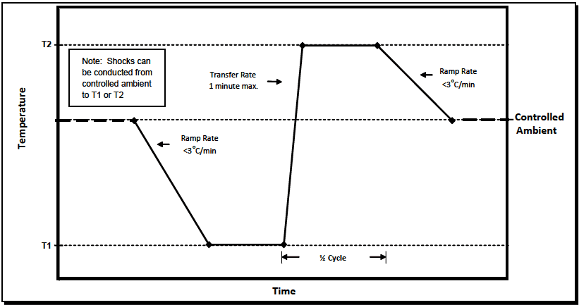
Figure description:
Temperature vs. Time Thermal Cycle Schematic
Thermal Cycle / Shock Profile
Annotations
- Note: Shocks can be conducted from controlled ambient to T1 or T2 (text_label - position: Upper left quadrant in a text box)
- Ramp Rate <3°C/min (text_label - position: On the descent from Controlled Ambient to T1)
- Transfer Rate 1 minute max. (text_label - position: On the rapid ascent from T1 to T2)
- ½ Cycle (dimension_line - position: Horizontal interval from end of low-temperature dwell to end of high-temperature dwell)
- Ramp Rate <3°C/min (text_label - position: On the descent from T2 to Controlled Ambient)
- Controlled Ambient (horizontal_line - position: y-axis middle, dashed horizontal line)
- T2 (horizontal_line - position: y-axis high, dotted horizontal line)
- T1 (horizontal_line - position: y-axis low, dotted horizontal line)
| Stage | Temperature Level | Rate / Duration Constraint |
|---|---|---|
| Start | Controlled Ambient | Initial starting state |
| Ramp Down | T1 | Ramp Rate < 3°C/min |
| Low Dwell | T1 | Duration from end of low dwell to end of high dwell is ½ Cycle |
| Rapid Transfer | T2 | Transfer Rate 1 minute max. |
| High Dwell | T2 | End of ½ Cycle |
| Ramp Down to Ambient | Controlled Ambient | Ramp Rate < 3°C/min |
Notes: The schematic illustrates a standard thermal stress profile involving ramp-down, dwell, rapid transfer (thermal shock, and ramp-down to ambient conditions. Diamond markers indicate key transition points in the temperature profile.)
Figure 503.7-1. Single Shocks (1/2 cycle).
4.4.2.2 Procedure I-B - Single Cycle Shock from Constant Extreme Temperature
- Step 1 With the test item in the chamber in its appropriate logistic configuration, adjust the chamber air temperature to the high or low temperature extreme specified in the test plan (T1) at a rate not to exceed 3 °C/min (5 °F/min). Stabilize the temperature for a period as determined in accordance with paragraph 2.3.5.
- Step 2 Transfer the test item in no more than one minute to an atmosphere at temperature (T2) that will produce the thermal shock specified in the test plan, and stabilize the temperature for a period as determined in accordance with paragraph 2.3.5.
- Step 3 If required in the test plan, evaluate the effects of the thermal shock on the test item to the extent practical.
- Step 4 Transfer the test item back to the T1 environment in no more than one minute. Stabilize the temperature for a period as determined in accordance with paragraph 2.3.5, and evaluate the thermal shock effects (if required).
|
Step 5 Return the test item to controlled ambient temperature conditions.
Step 6 Examine the test item and, if appropriate, perform an operational check. Record the results for comparison with pretest data. If the test item fails to operate as intended, see paragraph 5 for analysis of results.
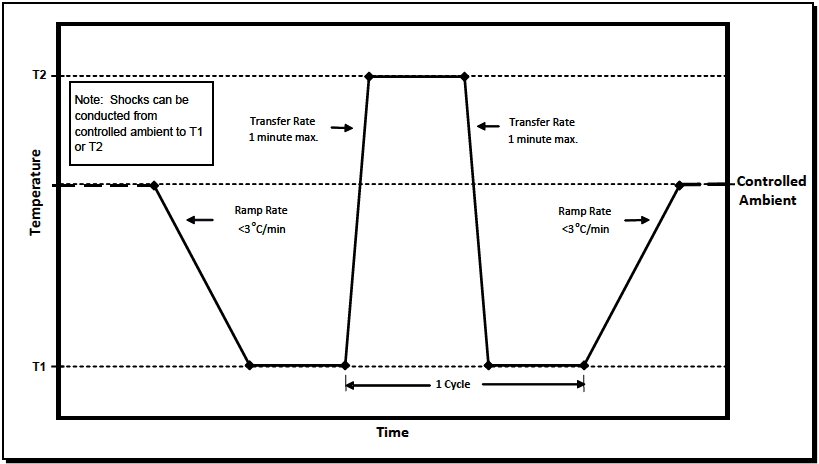
Figure description:
Temperature Cycle Profile Diagram
Temperature vs Time Profile
Annotations
- Note: Shocks can be conducted from controlled ambient to T1 or T2 (text_label - position: top-left corner box)
- Ramp Rate <3°C/min (text_label - position: along the ramp down from Controlled Ambient to T1)
- Transfer Rate 1 minute max. (text_label - position: along the rapid transfer up from T1 to T2)
- Transfer Rate 1 minute max. (text_label - position: along the rapid transfer down from T2 to T1)
- Ramp Rate <3°C/min (text_label - position: along the ramp up from T1 to Controlled Ambient)
- 1 Cycle (horizontal_range - position: From the start of the transfer to T2 until the end of the second dwell at T1)
- T2 (reference_line - position: y = T2 (dashed line))
- Controlled Ambient (reference_line - position: y = Controlled Ambient (dashed line))
- T1 (reference_line - position: y = T1 (dashed line))
| Event Point | Time Step (Ordinal) | Temperature | Phase / Description |
|---|---|---|---|
| P1 | 0 | Controlled Ambient | Start of profile |
| P2 | 1 | Controlled Ambient | End of initial hold / Start of ramp down |
| P3 | 2 | T1 | End of ramp down / Start of first dwell |
| P4 | 3 | T1 | End of first dwell / Start of 1 Cycle / Start of transfer up |
| P5 | 4 | T2 | End of transfer up / Start of dwell at T2 |
| P6 | 5 | T2 | End of dwell at T2 / Start of transfer down |
| P7 | 6 | T1 | End of transfer down / Start of second dwell |
| P8 | 7 | T1 | End of second dwell / End of 1 Cycle / Start of ramp up |
| P9 | 8 | Controlled Ambient | End of ramp up / Start of final hold |
| P10 | 9 | Controlled Ambient | End of profile |
Notes: The diagram outlines a thermal cycling process with specific ramp and transfer rate constraints, defining one cycle as the period from the start of the first transition to T2 until the beginning of the final ramp back to ambient.
Figure 503.7-2. Single Cycle Shocks.
4.4.2.3 Procedure I-C - Multi-Cycle Shocks from Constant Extreme Temperature
- Step 1 With the test item in the chamber in its appropriate logistic configuration, adjust the chamber air temperature to the high or low temperature extreme specified in the test plan (T1) at a rate not to exceed 3 °C/min (5 °F/min). Stabilize the temperature for a period as determined in accordance with paragraph 2.3.5.
Step 2 Transfer the test item in no more than one minute to an atmosphere at temperature (T2) that will produce the thermal shock specified in the test plan, and stabilize the temperature for a period as determined in accordance with paragraph 2.3.5.
Step 3 If required in the test plan, evaluate the effects of the thermal shock on the test item to the extent practical.
Step 4 Transfer the test item back to the T1 environment in less than one minute. Stabilize the temperature for a period as determined in accordance with paragraph 2.3.5, and evaluate the thermal shock effects (if required).
Step 5 Repeat steps 2-4 at least twice for a minimum of three cycles.
Step 6 Return the test item to controlled ambient temperature conditions.
Step 7 Examine the test item and, if appropriate, perform an operational check. Record the results for comparison with pretest data. If the test item fails to operate as intended, see paragraph 5 for failure analysis and follow the guidance in paragraph 4.3.2 for test item failure.
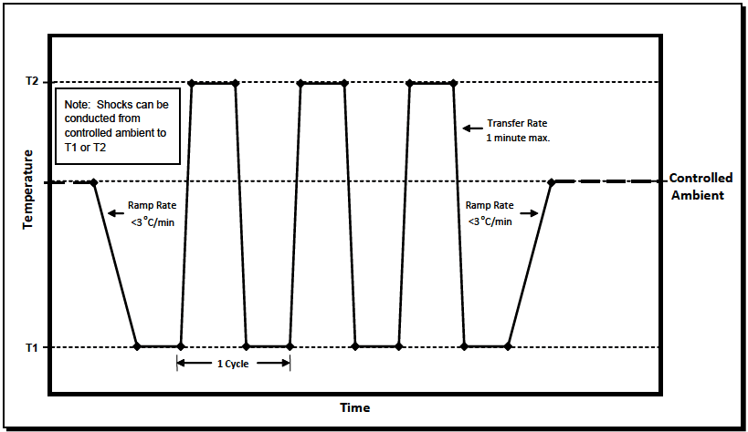
Figure description:
Thermal Cycle Test Profile
Temperature Cycle Profile
Annotations
- Note: Shocks can be conducted from controlled ambient to T1 or T2 (text_label - position: top-left)
- Ramp Rate <3°C/min (text_label - position: initial ramp down from Controlled Ambient to T1)
- Ramp Rate <3°C/min (text_label - position: final ramp up from T1 to Controlled Ambient)
- Transfer Rate 1 minute max. (text_label - position: downward transfer from T2 to T1)
- 1 Cycle (text_label - position: horizontal span from the start of the first ramp to T2 to the end of the first soak at T1)
- T1 (horizontal_line - position: y = T1 level)
- T2 (horizontal_line - position: y = T2 level)
- Controlled Ambient (horizontal_line - position: y = Controlled Ambient level)
| Step | Event | Temperature | Rate / Note |
|---|---|---|---|
| 1 | Start | Controlled Ambient | - |
| 2 | Start of Ramp Down | Controlled Ambient | - |
| 3 | End of Ramp Down | T1 | Ramp Rate < 3°C/min |
| 4 | Start of Soak at T1 | T1 | - |
| 5 | End of Soak / Start of Transfer Up | T1 | - |
| 6 | End of Transfer Up (Cycle 1) | T2 | Transfer Rate 1 minute max. |
| 7 | End of Soak / Start of Transfer Down | T2 | - |
| 8 | End of Transfer Down (Cycle 1) | T1 | Transfer Rate 1 minute max. |
| 9 | End of Soak / Start of Transfer Up | T1 | End of '1 Cycle' marker |
| 10 | End of Transfer Up (Cycle 2) | T2 | - |
| 11 | End of Soak / Start of Transfer Down | T2 | - |
| 12 | End of Transfer Down (Cycle 2) | T1 | - |
| 13 | End of Soak / Start of Transfer Up | T1 | - |
| 14 | End of Transfer Up (Cycle 3) | T2 | - |
| 15 | End of Soak / Start of Transfer Down | T2 | - |
| 16 | End of Transfer Down (Cycle 3) | T1 | - |
| 17 | End of Soak / Start of Ramp Up | T1 | - |
| 18 | End of Ramp Up | Controlled Ambient | Ramp Rate < 3°C/min |
| 19 | Final Soak | Controlled Ambient | - |
Notes: The chart illustrates a thermal cycling test profile over time. It specifies ramp rates for gradual temperature changes and transfer rates for rapid 'shock' changes between temperature extremes T1 and T2.
Figure 503.7-3. Multi-cycle Shocks.
4.4.2.4 Procedure I-D - Shocks To or From Controlled Ambient Temperature. (Figure 503.7-4)
NOTE: This procedural variation always starts at controlled ambient temperature conditions, but can be tailored to follow any of the three above variations, i.e., a single shock, a single cycle, or multiple cycles.
- Step 1 With the test item in its appropriate logistic configuration, stabilize the test item at controlled ambient temperature conditions. (Part One, paragraph 5.1).
- Step 2 Transfer the test item in no more than one minute to an atmosphere at temperature T1 or T2 that will produce the thermal shock specified in the test plan, and stabilize the temperature for a period as determined in accordance with paragraph 2.3.5.
- Step 3 Transfer the test item to controlled ambient temperature conditions in no more than one minute, and stabilize the temperature for a period as determined in accordance with paragraph 2.3.5.
- Step 4 If required in the test plan, evaluate the effects of the thermal shock on the test item to the extent practical.
- Step 5 Either tailor additional shocks by repeating steps 1-4, or proceed to Step 6.
- Step 6 After all required shocks are completed, examine the test item and, if appropriate, perform an operational check. Record the results for comparison with pretest data. If the test item fails to operate as intended, see paragraph 5 for analysis of results.
MIL-STD-810H
METHOD 503.7
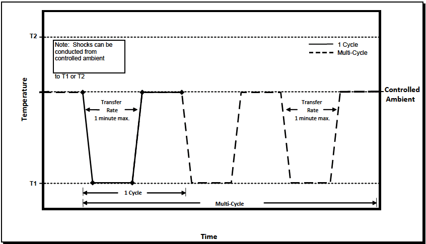
Figure description:
Thermal Shock Profile: Temperature vs. Time
Thermal Shock Temperature Profile
Legend
- 1 Cycle — color: black; symbol: Solid line
- Multi-Cycle — color: black; symbol: Dashed line
Annotations
- T2 (horizontal_line - position: y = T2)
- Controlled Ambient (horizontal_line - position: y = Controlled Ambient)
- T1 (horizontal_line - position: y = T1)
- Note: Shocks can be conducted from controlled ambient to T1 or T2 (text_label - position: top left quadrant)
- Transfer Rate 1 minute max. (text_label - position: Centered between Controlled Ambient and T1 on descent and ascent ramps)
- 1 Cycle (horizontal_interval - position: Duration of the first complete cycle (descent, hold, ascent, hold))
- Multi-Cycle (horizontal_interval - position: Total duration of multiple cycles)
| Relative Time | Temperature Level | Line Style | Series / Phase |
|---|---|---|---|
| 0 | Controlled Ambient | Solid | 1 Cycle Start |
| 1 | Controlled Ambient | Solid | 1 Cycle (Start Descent) |
| 2 | T1 | Solid | 1 Cycle (End Descent) |
| 3 | T1 | Solid | 1 Cycle (Start Ascent) |
| 4 | Controlled Ambient | Solid | 1 Cycle (End Ascent) |
| 5 | Controlled Ambient | Dashed | Multi-Cycle (Start Descent) |
| 6 | T1 | Dashed | Multi-Cycle (End Descent) |
| 7 | T1 | Dashed | Multi-Cycle (Start Ascent) |
| 8 | Controlled Ambient | Dashed | Multi-Cycle (End Ascent) |
| 9 | Controlled Ambient | Dashed | Multi-Cycle (Start Descent) |
| 10 | T1 | Dashed | Multi-Cycle (End Descent) |
| 11 | T1 | Dashed | Multi-Cycle (Start Ascent) |
| 12 | Controlled Ambient | Dashed | Multi-Cycle (End Ascent) |
Notes: The chart illustrates the temperature profile over time for thermal shock testing. It highlights key temperature thresholds (T1, T2, and Controlled Ambient and specifies a maximum transfer rate of 1 minute between these levels. The first cycle is depicted with a solid line and marker points at transitions, while subsequent cycles in a 'Multi-Cycle' test are shown with dashed lines.)
Figure 503.7-4. Shocks to & from Controlled Ambient.