4.1 Test Facility and Equipment
The following are requirements for performance of the basic rail impact test (see Figure 526.2-1).
4.1.1 Buffer Railcars
Loaded cars are preferred for use as the buffer or struck cars. However, empty cars may also be used. In either case, the total weight of the buffer cars shall be at least 113,400 kg (250,000 lb). The first buffer car must be a standard draft gear car. The remaining buffer cars should have standard draft gear, if possible. The AAR conducts ‘field rail impact tests’ at locations other than DoD test centers. For these ‘field rail impact tests’, unloaded buffer cars may be preferred so that the loads on/in the available buffer cars are not damaged during the impacts. The SDDCTEA needs to approve the use of loaded cars for a ‘field rail impact test’.
4.1.2 Test Railcar
Test railcars shall be equipped with chain tiedowns and end-of-car cushioned draft gear, unless other railcar types are approved by Director, SDDCTEA, Attn: SDTE-DPE, Building 1900W, 1 Soldier Way, Scott AFB, IL 62225. SDDCTEA is the designated DoD agent for land transportation. Some materiel may require other types of railcars for testing to be representative of the intended shipping methods.
MIL-STD-810H
METHOD 526.2
4.1.3 Locomotive
At least one locomotive or railcar mover capable of moving the railcars up to the required impact speeds. If a locomotive or railcar movers is not available see paragraph 4.1.5, Inclined Track.
4.1.4 Track
A minimum 61 m (200 ft) length of dry, level, tangent track is required between the buffer cars and test car to allow acceleration of locomotive and test car to specified impact speeds.
4.1.5 Inclined Track
If a locomotive is not available to accelerate the test car, use an inclined tangent track in lieu of a locomotive.
4.2 Controls
- a. Load and secure the test item as would be done for actual rail transport. All contact areas of the test item railcar, lading, and securement items must be free of ice, snow and debris. The tiedown provisions shall provide the entire restraint of the test item without any other restraint such as blocking, vehicle brakes or other added material. If safety or other reasons preclude the use of a test item representative of the secondary load, use a substitute test item that is equal in weight and similar dynamic characteristics to the materiel. Prior to using a substitute test item, obtain approval from SDDCTEA.
- (1) Wheeled Vehicles. Tires must be inflated as uniformly as possible to the tire manufacturer’s recommended highway pressures.
- (2) Trailers. Unless otherwise specified in the detailed test plan and approved by SDDCTEA, trailers should be tested both connected to and disconnected from their prime mover. When the trailer is tested disconnected from its prime mover, secure it to the railcar either with the lunette resting on the deck (the lunette may need insulation/padding to prevent metal-on-metal contact with the deck of the railcar), landing legs extended, or tested as a Trailer-On-Flatcar (TOFC), whichever is appropriate. Lumber or hardware that are not a Basic Issue Item (BII) for the trailer may not be added. This prohibits the use of wooden stanchions.
- (3) Vehicle Fuel Tanks. Ensure all fuel tanks for test items are approximately 3/4 full during the test (see paragraph 6.1, reference d).
- (4) Fuel and other Bulk Liquid Tankers. Unless otherwise specified in the requirements documents, fuel and other bulk liquid tankers should be subjected to Rail Impact testing at both 60 percent full and fully loaded conditions. The maximum sloshing force is generated when the liquid fill percentage is close to 60 percent. Therefore, for tank vehicles, a liquid fill percentage close to 60 percent is the worst laden state (see paragraph 6.1, reference e). If it is desired, or there is a need, to use a substitute for fuel (i.e. HAZMAT concerns), contact SDDCTEA for approval.
- (5) Variable height or pneumatic suspensions. Vehicles may be equipped with either variable height or pneumatic suspensions. Variable height suspensions must be lowered into transport mode and pneumatic suspensions must be bled prior to securing the vehicle to the railcar so that the vehicle is resting on hard stops. If applicable, all manually inserted suspension stops must be inserted and secured. This is done to prevent air suspensions from leaking and losing pressure causing the vehicle to lower significantly in transit and introduce an unsafe amount of chain slack.
- b. Unless otherwise specified in the transportability requirements for the materiel, perform the test with the test item at its maximum gross weight (fully loaded) rating. Exceptions to including payload as part of the vehicle weight are vehicles that do not carry a payload during transport such as wreckers, dump trucks, and material handling equipment.
- c. When testing a vehicle(s) ensure the parking brake(s) is released and the transmission(s) is placed in the neutral position. This ensures the transmission and the brakes are not part of the test item securement. Vehicles equipped with air brakes should have the brake system pressurized (brakes released). This will validate the restraint method for the worst case condition - no brakes applied. Vehicle restraint would be enhanced if a vehicle’s air brake system were to bleed causing the brakes to engage in route during actual rail transport.
MIL-STD-810H
METHOD 526.2
4.3 Test Interruption
Test interruptions can result from two or more situations, one being from a failure or malfunction of test facilities or associated test laboratory equipment. The second type of test interruption results from securement failure or malfunction of the test item itself during required or optional performance checks.
4.3.1 Interruption Due To Facility Malfunction
- a. General. See Part One, paragraph 5.11, of this standard.
- b. Specific to this method.
- (1) Undertest interruption. If an unscheduled interruption occurs that causes the test conditions to fall below allowable limits, the test must be reinitiated at the end of the last successfully completed cycle.
- (2) Overtest interruption. If the test item(s) is exposed to test conditions that exceed allowable limits, conduct an appropriate physical examination of the test item and perform an operational check (when practical) before testing is resumed. This is especially true where a safety condition could exist, such as with munitions. If a safety condition is discovered, the preferable course of action is to terminate the test and reinitiate testing with a new test item. If this is not done and test item failure occurs during the remainder of the test, the test results may be considered invalid. If no problem has been encountered, reestablish pre-interruption conditions and continue from the point where the test tolerances were exceeded.
4.3.2 Interruption Due To Test Item Or Securement Failure
Failure of the test item(s) or items of securement to function as required during performance checks during testing presents a situation with two possible options.
- a. The preferable option is to replace the test item with a “new” item and restart from Step 1.
- b. A second option is to replace/repair the failed or non-functioning component or assembly with one that functions as intended, and restart the test from Step 1.
- c. In the event of a securement failure, re-secure and/or add additional tiedowns approved by SDDCTEA prior to continuation of testing and restart the test from Step 1. Only use an arrangement of the test item and its tiedown to be tested that is identical to that proposed or approved by SDDCTEA.
NOTE: When evaluating failure interruptions, consider prior testing on the same test item and consequences of such.
4.4 Test Setup
- a. Buffer car(s) must have their air and hand brakes set. This provides a more conservative test. Cars must be bunched with a locomotive or railcar mover to compress all slack and cushioning in the couplings, if any. The struck end of the first buffer car must have standard draft gear.
- b. Locate the test car between the buffer car(s) and the locomotive or railcar mover.
- c. Install one of the following timing devices (or equivalent) to obtain the impact speed of the test car.
- (1) An electric timing system capable of measuring within ±0.16 km/h (±0.1 mph): Place the switch contacts on the track in accordance with manufacturer's instructions.
- (2) Radar: In order to obtain an accurate speed, position the radar in line with the direction of impact or as otherwise recommended by the radar manufacturer. Verify that the radar can accurately measure speeds in the 5.6 km/h to 13.7 km/h (3.5 to 8.5 mph) range with a tolerance of ±0.16 km/h (±0.1 mph). For safety, the radar operator should be positioned so as to aim at the test car moving away from their position.
- (3) A speed sensor (GPS based or other) located on the test car capable of measuring within ±0.16 km/h (±0.1 mph).
MIL-STD-810H
METHOD 526.2
The speed measuring device must have a current and verifiable calibration certificate.
- d. Photograph the test setup including any securement items. This may be a valuable tool if there is any subsequent failure of the items of securement.
4.4.1 Preparation for Test
- a. The materiel developer is responsible for the development of transportation procedures and instructions, and is responsible for coordinating these with and obtaining approval from SDDCTEA well in advance of rail impact testing. Inspect all chain assemblies for signs of stretching, gouging, or other damage to include the compression units. Mount and secure the test item as would be done in actual service and in accordance with the standard loading methods shown in paragraph 6.1, reference a, and Figure 526.2-1. Do not use more than four tiedown provisions, typically two at each end of the test item as defined by MIL-STD-209, Lifting and Tiedown Provisions (see paragraph 6.1, reference g). If the item requires more than four tiedown provisions, approval to deviate from MIL-STD-209 is needed from SDDCTEA prior to testing. Place the vehicle(s) on the flatcar so the tiedown chain makes approximately a 45 degree angle with the flatcar's deck when viewed from the side. Measuring by eye is usually good enough. To layout the correct angle with a tape measure, make the longitudinal distance from the point the tiedown attaches to the deck to the tiedown provision on the vehicle equal to the vertical distance from the deck to the provision (Figure 526.2-2). Do not cross tiedowns unless prior approval is granted by SDDCTEA. Once all chain tiedowns are secure, assure proper tension in all tiedowns. A properly tensioned tiedown will not tighten a compression unit such that there is no gap (go solid) that eliminates the shock mitigation. Only use an arrangement of the test item and its tiedown to be tested that is identical to that proposed or approved by SDDCTEA.
- b. If required, install transducers on the test railcar and test item sufficient to measure acceleration and any other required parameters. Protect transducers to prevent contact with surfaces other than the mounting surface.
- c. If appropriate, perform an operational test to establish baseline data to be used in post-test analysis.
4.5 Test Tolerances
Ensure test tolerances are in accordance with tolerances specified in paragraphs 4.4 and 4.6, and in the test plan.
4.6 Rail Impact Procedure
The method for accelerating the test car will vary depending on the test facility. Typically, the test car can be accelerated using a locomotive or an inclined track. Use the steps below that apply to your test facility.
- Step 1a (Locomotive). Brief the train crew on the procedure. Delegate one person to advise the appropriate member of the train crew when moves are to be made. Instruct all participants and observers to take precautions for their personal safety and observe safety practices of the carrier and/or company conducting the test. If desired, perform a test run without impacting the test item to establish accuracy of speed.
Step 1b (Inclined track). A section of track can be calibrated using a test car and speed-measuring device. Release the test car from the designated starting point and allow it to roll freely down the inclined track. Drop markers at the locations where the test car reaches the desired speeds. Ensure no other cars are present on the test track during the calibration process. Repeat the process at least twice to ensure the accuracy of speed locations. Next, release the test car from the same starting point and make adjustments in markers if needed prior to impacting. Speeds still need to be measured during the actual test as described above in paragraph 4.4c.
- Step 2a (Locomotive). Pull the rail car carrying the test item a sufficient distance from the buffer cars. Next, push the test load car toward the buffer car(s) until the desired speed is obtained, and release it so it rolls freely into the buffer car(s) - having knuckles open and positioned for coupling.
- Step 2b (Inclined track). After determining speed locations, perform impacts by locating the buffer cars at the proper location for desired impact speed, and for releasing the test car from the designated starting point. This requires moving the buffer cars every time a different speed is required. In lieu of repositioning of the buffer cars at various positions on the track, release the test car from calibrated positions on the inclined track that correspond to the desired speeds.
MIL-STD-810H METHOD 526.2
RAIL IMPACT TEST Test Car Buffer Car(s) Minimum Total Weight of 250,000 lbs. Test Item Loaded to Maximum Gross Weight Rating Standard Draft Gear Upweighted Railcar with brakes set Cushioned Draft Gear Test Item Use of locomotive or inclined track Test Impact Speed and Direction
- Forward 4, 6, and 8 mph Direction of Travel
- Reverse 8 mph
- Loading - load and secure the item as would be done for actual rail transport.
- Fuel Tanks - ensure vehicle fuel tanks for test item are approximately ¼ full during test.
- When testing vehicles - ensure the parking brakes are released and the transmission is placed in the neutral position. This ensures the transmission and the brakes are not part of the test item securement.
- Trailers - connect any trailers to their prime mover if there is adequate space on the test car.
- Buffer Car - must have their air and hand brakes set.
- Track - minimum of 61m (200 ft) length of dry, level tangent track is required between the buffer car and the test car to allow acceleration of the locomotive and test car to specified speeds.
- Tiedowns - cannot be adjusted between impacts.
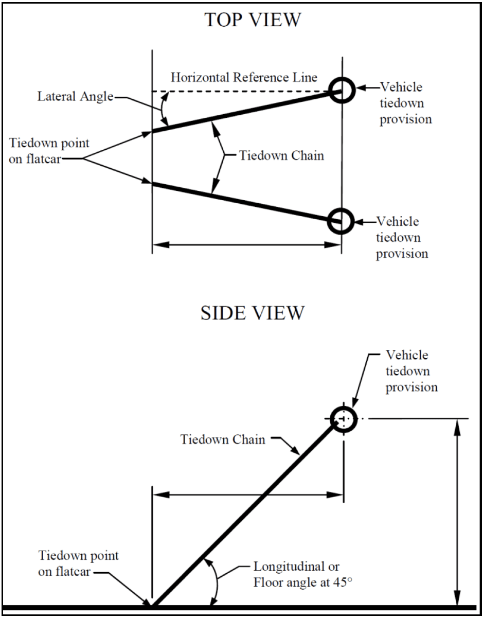
Figure description:
Top View
- Entities: Vehicle tiedown provisions, tiedown chains, and tiedown points on the flatcar.
- Details: Illustrates two chains diverging from the flatcar points to the vehicle. Identifies a lateral angle relative to a horizontal reference line.
Side View
- Entities: Vehicle tiedown provision, tiedown chain, and tiedown point on the flatcar.
- Details: Shows a longitudinal or floor angle of 45°. The vertical height and horizontal distance between the flatcar point and the vehicle provision are equal.
Figure 526.2-2. Tiedown chain angle of 45 degrees in the side view; the dimensions shown are all equal.
Step 3 Subject the test item to four impacts, the first three of which are in the same direction and at speeds of 6.4, 9.7, and 12.9 km/h (4, 6, and 8 mph) respectively, each speed with a tolerance of ±0.8 km/h (±0.5 mph) for the 6.4 and 9.7 km/h impacts, and +0.8, -0.0 km/h (+0.5, -0.0 mph) for the 12.9 km/h impacts. Perform the fourth impact at 12.9 km/h (+0.8, -0.0 km/h) (8 mph (+0.5, -0.0 mph)) impacting the opposite end of the test car from the first three impacts. If it is not possible to turn the test car because of track layout, this may be accomplished by running the test item car to the opposite end of the buffer cars and impacting as above.
Step 4 If the lading or securement items loosen or fail during the test, photograph and document these items. If it appears necessary to adjust the lading or securement items to continue the test, correct the restraint and restart the test from the beginning and follow the guidance provided in paragraph 4.3.2.
Step 5 If the materiel can be shipped in two orientations (such as lengthwise and crosswise on the rail car), repeat the four impacts for each orientation or have two test items on the test railcar one mounted in each orientation.
Step 6 Perform a posttest operational check for comparison with pre-test data, and see paragraph 5 for analysis of results.
4.7 Additional Requirements
Step 1 Repeat any impacts that are below the required test speeds. If any readjustment of the lading or reconditioning of the bracing or items of securement is necessary, correct, photograph, and document the problem(s), correct the restraint, and restart the entire test beginning with the 6.4 km/h (4 mph) impact. Accept any impacts above the required test speed providing the test item satisfies the requirements of paragraph 5.
Step 2 If the tiedown chains become loose, or if there is visible permanent deformation of the tiedown chains during the test, photograph and document the problem(s). The test officer will notify SDDCTEA of the modifications required, and jointly decide if a retest is required.