| Bearing Property Reduction, percent | |
|---|---|
| Thickness (in.) | 1.001-6.000 |
| Fbru (e/D = 1.5) | 15 |
| Fbru (e/D = 2.0) | 10 |
| Fbry (e/D = 1.5) | 5 |
| Fbry (e/D = 2.0) | 5 |
bearing specimens are oriented so the width of the specimens is normal to the parting plane (edgewise). The specimens are positioned so the bearing test holes are midway between the parting plane and the top of the flange. The severity of metal flow at the parting plane near the flash can be expected to vary considerably for web-flange type die forgings; therefore, for consistency, the bearing test hole should not be located on the parting plane. However, in the case of large, bulky-type die forgings, with a cross-sectional shape similar to a square, rectangle, or trapezoid, as shown in Figure 3.1.2.1.1(c), longitudinal bearing specimens are oriented edgewise to the parting plane, but the specimens are positioned so the bearing test holes are located on the parting plane. Similarly, for hand forgings, bearing specimens are oriented edgewise and the specimens are positioned at the thickness location.
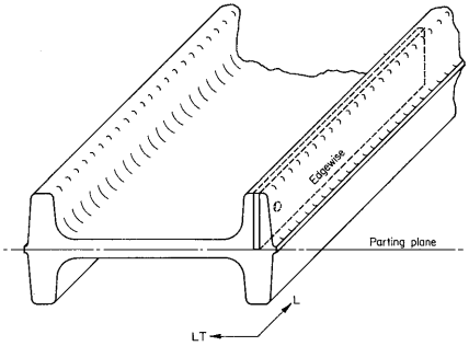
Figure description:
- Subject: Bearing specimen orientation for web-flange type die forging.
- Key Entities:
- Web-Flange Die Forging: The main structural body shown in cross-section.
- Parting Plane: Indicated by a dashed horizontal line through the center of the web.
- Bearing Specimen: Labeled "Edgewise," oriented vertically with its width normal to the parting plane.
- Bearing Test Hole: Located midway between the parting plane and the top of the flange.
- Orientation Axes: Longitudinal (L and Long Transverse (LT directions are indicated.
Figure 3.1.2.1.1(b). Bearing specimen orientation for web-flange type die forging.
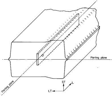
Figure description:
Key Information:
- Subject: Diagram of bearing specimen orientation for a thick cross-section die forging.
- Parting Plane: A horizontal reference line bisecting the forged section.
- Specimen Placement: A rectangular test specimen is shown oriented vertically across the parting plane.
- Directional Axes:
- L: Longitudinal direction.
- LT: Long Transverse direction.
- ST: Short Transverse direction.
- Orientation Detail: the specimen's primary length is aligned with the longitudinal (L axis, while its height spans the short transverse (ST direction across the parting plane.
Figure 3.1.2.1.1(c). Bearing specimen orientation for thick cross-section die forging.