5.6.1
BEAMS — See Equation 1.3.2.3, Section 1.5.2.5, and References 1.7.1(a) and (b) for general information on stress analysis of beams.
5.6.1.1
Simple Beams — Beams of solid, tubular, or similar cross sections can be assumed to fail through exceeding an allowable modulus of rupture in bending ( ). In the absence of specific data, the ratio can be assumed to be 1.25 for solid sections.
5.6.1.1.1
Round Tubes — For round tubes, the value of will depend on the D/t ratio as well as the ultimate tensile stress. The bending modulus of rupture of 6Al-4V titanium alloy is given in Figure 5.6.1.1.1.
5.6.1.1.2
Unconventional Cross Sections — Sections other than solid or tubular should be tested to determine the allowable bending stress.
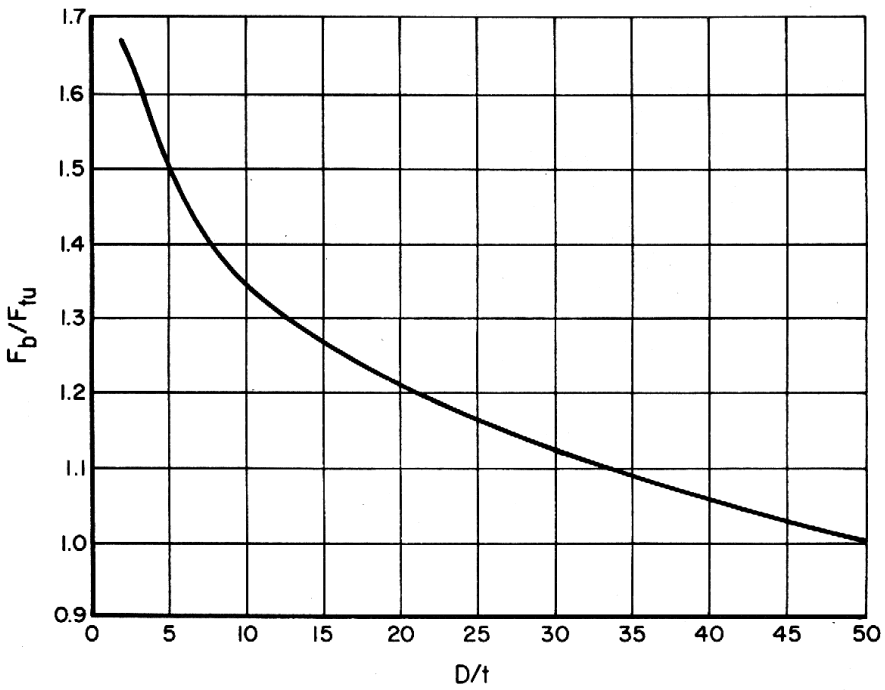
Figure description:
Relationship between D/t and Fb/Ftu
| D/t | Fb/Ftu |
|---|---|
| 2 | 1.67 |
| 5 | 1.50 |
| 7.5 | 1.41 |
| 10 | 1.35 |
| 12.5 | 1.30 |
| 15 | 1.27 |
| 17.5 | 1.24 |
| 20 | 1.21 |
| 25 | 1.16 |
| 30 | 1.12 |
| 35 | 1.09 |
| 40 | 1.06 |
| 45 | 1.03 |
| 50 | 1.00 |
Notes: The chart displays a curved line showing how the ratio of bending stress to ultimate tensile strength (Fb/Ftu decreases as the ratio of diameter to thickness (D/t increases. The x-axis represents D/t from 0 to 50, and the y-axis represents Fb/Ftu from 0.9 to 1.7.))
Figure 5.6.1.1. Bending modulus of rupture for solution-treated and aged Ti-6Al-4V alloy round tubing manufactured from bar material.