6.4.0
GENERAL COMMENTS — The use of cobalt in wrought heat-resistant alloys is usually limited to additions of cobalt to alloys of other bases. Very few of the heat-resistant alloys can be considered as cobalt base, since cobalt is seldom the predominating element. For airframe applications, some workability is usually required; the alloys considered in this section are limited to those available in wrought form.
6.4.0.1 Metallurgical Considerations
Composition — The common alloying elements for cobalt are chromium, nickel, carbon, molybdenum, and tungsten. Chromium is added to increase strength and oxidation resistance at very high temperatures; nickel to increase toughness; carbon to increase the hardness and strength, especially when combined with chromium and the other carbide formers, molybdenum and tungsten; molybdenum and tungsten also contribute to solid-solution strengthening.
Vacuum melting is not required for these alloys. For this reason, the cobalt-base alloys are often competitively priced with vacuum-melted nickel-base alloys although the price of cobalt is higher than that of nickel.
Heat Treatment — The cobalt-base alloys are heat treated with conventional equipment and fixtures such as those used with austenitic stainless steels. The use of good heat-treating practices is recommended, although this is not so critical as in the case of the nickel-based alloys.
6.4.0.2 Manufacturing Considerations
Forging — Because these alloys are designed to have very high strength at temperatures near the forging range, they require the use of heavy forging equipment. However, the forgeability of these alloys is good over a fairly wide range of temperatures. Hot-cold working is neither required nor recommended for these alloys.
Cold Forming — These alloys, when in the solution-treated condition, have excellent ductility and are readily cold formed. Because of their capacity for work hardening, they require higher forming pressures and frequent anneals.
Machining — These alloys are tough and they work harden rapidly; consequently, heavy-duty vibration-free machine tools, sharp cutting tools (high-speed steel or carbide tipped), and low cutting speeds are required.
Welding — The weldability of the cobalt-base alloys is comparable with that of the austenitic stainless steels. Welding may be accomplished by all commonly used welding processes. Large or complex weldments require stress relief.
Brazing — These alloys can be brazed using the same techniques and precautions applicable to stainless steels and nickel-base alloys. Alloys which contain aluminum or titanium require extremely dry, inert gas atmospheres, very high vacuum or a thin (0.002 to 0.0010 inch thick) nickel plating to prevent surface oxidation. It is also necessary to braze the material in the annealed condition and to keep the stresses low during brazing to avoid embrittlement, especially when brazing with low melting alloys.
6.4.0.3
Special Precautions — If the cobalt-base alloys have not been exposed to neutron radiation, no special safety precautions in handling are required. However, neutron irradiation creates a very dangerous radioactive isotope, cobalt 60, which has a half life of about 5.2 years. Special precautions must be employed to protect personnel from the radioactive material.
MIL-HDBK-5J
6.4.1 L-605
6.4.1.0
Comments and Properties — L-605, also known as Haynes Alloy 25, is a corrosion and heat-resistant cobalt-base alloy used for moderately stressed parts operating between 1000 and 1900°F. Its applications include gas turbine blades and rotors, combustion chambers, and afterburner parts. L-605 is not hardenable except by cold working and is usually used in the annealed condition. It is available in all the usual mill forms.
L-605 forges moderately well between 1900°F and 2250°F. In the annealed condition, it has excellent formability at room temperature; severely formed parts should be annealed at 2225°F for 7 to 10 minutes. L-605 is difficult to machine. Its toughness and capacity for work hardening necessitate the use of sharp tools and low cutting speeds; high-speed steel or carbide cutting tools are recommended. L-605 can be fusion or resistance welded or brazed; large or complex fusion weldment should be stress relieved at 1300°F for 2 hours. This alloy has excellent oxidation resistance up to 1900°F.
Some material specifications for L-605 are shown in Table 6.4.1.0(a). Room-temperature mechanical and physical properties are shown in Table 6.4.1.0(b). The effect of temperature on physical properties is shown in Figure 6.4.1.0.
| Specification | Form | Condition |
|---|---|---|
| AMS 5537 | Sheet | Solution treated (annealed) |
| AMS 5759 | Bar and forging | Solution treated (annealed) |
6.4.1.1
Solution Treated Condition — Elevated temperature properties for this condition are shown in Figures 6.4.1.1.1 through 6.4.1.1.5. A creep nomograph is shown in Figure 6.4.1.1.7. Stress-rupture requirements at elevated temperatures are specified in material specifications. The appropriate specification should be consulted for detailed requirements.
MIL-HDBK-5J
31 January 2003
| Specification | AMS 5537 | AMS 5759 | ||
|---|---|---|---|---|
| Form | Sheet | Plate | Bar and forging | |
| Condition | Solution treated | |||
| Thickness, in. | 0.010-0.187 | 0.188-0.375 | ≤ 1.000 | |
| Basis | A | B | S | S |
| Mechanical Properties: | ||||
| Ftu, ksi: | ||||
| L | 126 | 131 | 125 | |
| LT | 130 | 135 | 130 | |
| Fty, ksi: | ||||
| L | 57 | 62 | 45 | |
| LT | 55a | 60 | 55 | |
| Fcy, ksi: | ||||
| L | 41 | 45 | 42 | |
| LT | 56 | 61 | ||
| Fsu, ksi | 91 | 95 | 91 | 88 |
| Fbru, ksi: | ||||
| (e/D = 1.5) | 186 | 193 | 186 | |
| (e/D = 2.0) | 232 | 241 | 232 | |
| Fbry, ksi: | ||||
| (e/D = 1.5) | 88 | 96 | 88 | |
| (e/D = 2.0) | 113 | 123 | 113 | |
| e, percent (S-basis): | ||||
| L | 30 | |||
| LT | b | 45 | ||
| E, 103 ksi | 32.6 | |||
| Ec, 103 ksi | 32.6 | |||
| G, 103 ksi | 12.6 | |||
| μ | 0.29 | |||
| Physical Properties: | ||||
| ω, lb/in.3 | 0.330 | |||
| C, Btu/(lb)(°F) | 0.090 (70-212°F) See Figure 6.4.1.0 | |||
| C, K, and α | ||||
MIL-HDBK-5J
6.4.2 HS 188
6.4.2.0
Comments and Properties — HS 188 is a corrosion- and heat-resistant cobalt-base alloy used for moderately stressed parts up to 2100°F. The alloy exhibits outstanding oxidation resistance up to 2100°F resulting from the addition of minute amounts of lanthanum to the alloy system. The alloy exhibits excellent post-aged ductility after prolonged heating of 1000 hours at temperatures up to 1600°F inclusive.
HS 188 is not hardenable except by cold working and is used in the solution-treated condition. The alloy can be forged and welded. Welding can be accomplished by both manual and automatic welding methods including electron beam, gas tungsten air, and resistance welding. Like other cobalt base alloys, machining is difficult necessitating the use of sharp tools and low cutting speeds; high speed steel or carbide cutting tools are recommended. Gas turbine applications include transition ducts, combustion cans, spray bars, flame-holders, and liners.
Material specifications for HS 188 are presented in Table 6.4.2.0(a). Room-temperature mechanical and physical properties are shown in Table 6.4.2.0(b). The effect of temperature on physical properties is shown in Figure 6.4.2.0.
| Specification | Form | Condition |
|---|---|---|
| AMS 5608 | Sheet and plate | Solution treated (annealed) |
| AMS 5772 | Bar and forging | Solution treated (annealed) |
6.4.2.1
Solution-Treated Condition — Elevated-temperature properties are presented in Figures 6.4.2.1.1(a) and (b), 6.4.2.1.2, 6.4.2.1.4(a) through (c), and 6.4.2.1.5. Typical tensile stress-strain curves at room temperature are presented in Figure 6.4.2.1.6(a). Typical compressive stress-strain and tangent-modulus curves at room and elevated temperatures are presented in Figure 6.4.2.1.6(b). Strain control fatigue data for bar are presented in Figures 6.4.2.1.8(a) through (d).
MIL-HDBK-5J
31 January 2003
| Specification | AMS 5608 | |
|---|---|---|
| Form | Sheet | |
| Condition | Solution Treated | |
| Thickness, in. | <0.020 | 0.020-0.187 |
| Basis | S | S |
| Mechanical Properties: | ||
| Ftu, ksi: | ||
| L | 125 | 125 |
| LT | 125 | 125 |
| Fty, ksi: | ||
| L | 57 | 57 |
| LT | 55 | 55 |
| Fcy, ksi: | ||
| L | ||
| LT | 55 | 55 |
| Fsu, ksi: | 111 | 111 |
| Fbru, ksi: | ||
| (e/D = 1.5) | ||
| (e/D = 2.0) | ||
| Fbry, ksi: | ||
| (e/D = 1.5) | ||
| (e/D = 2.0) | ||
| e, percent: | ||
| LT | 40 | 45 |
| E, 10³ ksi | 33.6 | |
| Ec, 10³ ksi | 33.6 | |
| G, 10³ ksi | 12.8 | |
| μ | 0.31 | |
| Physical Properties: | ||
| ω, lb/in.³ | 0.324 | |
| C, K, and α | See Figure 6.4.2.0 | |
from https://
MIL-HDBK-5J
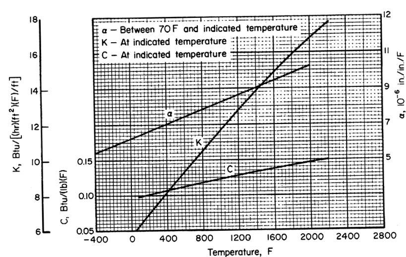
Figure description:
Material Properties vs. Temperature
Material Properties vs. Temperature
Legend
- ̑ - Between 70 F and indicated temperature — color: black; symbol: Solid line
- K - At indicated temperature — color: black; symbol: Solid line
- C - At indicated temperature — color: black; symbol: Solid line
Annotations
- ̑ (text_label - position: Near the line for ̑ at Temperature ≈ 400)
- K (text_label - position: Near the line for K at Temperature ≈ 800)
- C (text_label - position: Near the line for C at Temperature ≈ 1200)
| Temperature (F) | ̑ (10⁻⁶ in./in./F) | K (Btu/[(hr(ft²(F/ft)))) | C (Btu/(lb(F))) |
|---|---|---|---|
| -400 | 5.3 | null | null |
| -200 | 5.6 | null | null |
| 0 | 6.0 | null | null |
| 100 | 6.2 | 6.0 | 0.100 |
| 200 | 6.4 | 6.7 | 0.103 |
| 400 | 6.8 | 8.0 | 0.108 |
| 600 | 7.2 | 9.3 | 0.113 |
| 800 | 7.5 | 10.6 | 0.118 |
| 1000 | 7.9 | 11.9 | 0.123 |
| 1200 | 8.3 | 13.2 | 0.128 |
| 1400 | 8.7 | 14.5 | 0.133 |
| 1600 | 9.0 | 15.8 | 0.138 |
| 1800 | 9.4 | 17.1 | 0.143 |
| 2000 | 9.8 | 18.4 | 0.148 |
| 2200 | 10.2 | null | 0.153 |
Notes: The chart features multiple Y-axes: ̑ is on the right axis, K is on the outermost left axis, and C is on the inner left axis. Data values are estimated based on the provided grid.
Temperature, F
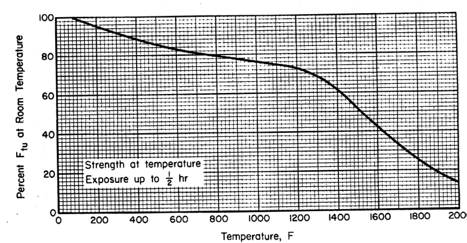
Figure description:
Material Strength at Elevated Temperatures Percentage of Room Temperature Ftu vs. Temperature
Strength at temperature
Annotations
- Strength at temperature Exposure up to 1/2 hr (text_label - position: x=200 to 800, y=20 to 30)
| Temperature (F) | Percent F_tu at Room Temperature |
|---|---|
| 0 | 100.0 |
| 100 | 97.5 |
| 200 | 95.0 |
| 300 | 92.5 |
| 400 | 90.0 |
| 500 | 87.5 |
| 600 | 85.0 |
| 700 | 82.5 |
| 800 | 80.0 |
| 900 | 78.5 |
| 1000 | 77.0 |
| 1100 | 75.5 |
| 1200 | 73.0 |
| 1300 | 68.0 |
| 1400 | 62.0 |
| 1500 | 52.0 |
| 1600 | 42.0 |
| 1700 | 33.0 |
| 1800 | 26.0 |
| 1900 | 20.0 |
| 2000 | 15.0 |
Notes: The chart illustrates the reduction in the ultimate tensile strength (Ftu of a material as a percentage of its room temperature value when exposed to elevated temperatures up to 2000 degrees Fahrenheit for a duration of up to 30 minutes.)
Figure 6.4.2.1.1(a). Effect of temperature on tensile ultimate strength (Ftu) of HS 18 sheet.