4.4.1
BEAMS — Refer to Chapter 1 and References 1.7.1(a) and (b) for general information on stress analysis of beams.
4.4.1.1
Simple Beams — Beams of solid tubular, or similar cross sections can be assumed to fail through exceeding an allowable modulus of rupture in bending (Fb). In the absence of specific data, the ratio Fb/Ftu can be assumed to be 1.25 for solid sections.
4.4.1.1.1
Round Tubes — For round tubes, the value of will depend on the D/t ratio as well as the compressive yield stress.
4.4.1.1.2
Unconventional Cross Sections — Sections other than solid or tubular should be tested to determine allowable bending stress.
4.4.1.2
Built-Up Beams — Built-up beams will usually fail because of local failure of component parts.
4.4.1.3
Thin-Web Beams — The allowable stress for thin-web beams will depend on the nature of the failure and are determined from the allowable stress of the web in tension and of the flanges or stiffeners in compression.
4.4.2 COLUMNS
4.4.2.1
Primary Failure — The general formula for primary instability is given in Section 1.3.8. Formulas applicable to magnesium-alloy columns are given in Tables 4.4.2.1(a) and (b). See References 4.4.2(a) and (b).
Table 4.4.2.1(a). Column Formula for Magnesium-Alloy Extruded Open Shapes
General Formulaa
(Stress values are in ksi)
| Alloy | K | n | m | Max. P/A |
|---|---|---|---|---|
| AZ31B, AZ61A | 2,900 | ¼ | 1.5 | Fcy |
| ZK60A-T5 | 3,300 | ¼ | 1.5 | 0.96 Fcy |
aFormula is for members that do not fail by local buckling. See Figure 4.4.2.3(a).
MIL-HDBK-5J
4.4.2.2 Local Failure
4.4.2.3
Column Properties — Curves of the allowable column stresses for various magnesium alloy columns are given in Figures 4.4.2.3(a) and (b). The allowable stress is plotted against the effective slenderness ratio defined by Equation 3.10.2.3.
MIL-HDBK-5J
4.4.3 TORSION
4.4.3.1
General — The general statements relating to aluminum-alloy tubing in 3.10.3 are applicable to magnesium tubing.
4.4.3.2
Torsion Properties — An empirical curve of the allowable torsional modulus of rupture for AZ62A-F magnesium-alloy round tubing (specification WW-T-825) is given in Figure 4.4.3.2.
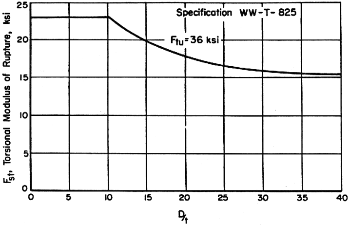
Figure description:
Torsional Modulus of Rupture vs D/t
Annotations
- Specification WW-T- 825 (text_label - position: top right quadrant)
- Ftu = 36 ksi (text_label - position: pointing to the curve at D/t ≈ 20, Fst ≈ 18)
| D/t | Fst, Torsional Modulus of Rupture (ksi) |
|---|---|
| 0 | 23.0 |
| 5 | 23.0 |
| 10 | 23.0 |
| 15 | 20.0 |
| 20 | 17.8 |
| 25 | 16.6 |
| 30 | 15.8 |
| 35 | 15.4 |
| 40 | 15.2 |
Notes: The chart shows the relationship between the ratio D/t and the torsional modulus of rupture (Fst for Specification WW-T-825, specifically for Ftu = 36 ksi.)
Figure 4.4.3.2. Torsional modulus of rupture for AZ61A-F magnesium-alloy round tubing.