2.8.1 BEAMS
See Equation 1.3.2.3, Section 1.5.2.5, and References 1.7.1(a) and (b) for general information on stress analysis of beams.
2.8.1.1
Simple Beams — Beams of solid, tubular, or similar cross sections, not subject to instability (buckling, crippling, column, lateral bending) can be assumed to fail through exceeding an allowable modulus of rupture in bending, , the value of which will depend upon beam cross-section geometry and beam material stress-strain characteristics. The modulus of rupture in bending is further discussed in Section 1.5.2.5. See Reference 2.8.1.1.
Round Tubes — For round tubes, the value of will depend on the D/t ratio, as well as the ultimate tensile stress. Figures 2.8.1.1(a) and (b) give the bending modulus of rupture for round alloy-steel tubing.
Unconventional Cross Sections — Sections other than solid or tubular should be tested to determine the allowable bending stress.
2.8.1.1
Ades, C. S., "Bending Strength of Tubing in the Plastic Range," Journal of the Aeronautical Sciences, Vol. 24, pp 605-610 (1957).
MIL-HDBK-5J
2.8.1.2
Built-Up Beams — Built-up beams usually fail because of local failures of the component parts. In welded steel tube beams, the allowable tensile stresses should be reduced properly for the effects of welding.
2.8.1.3
Thin-Web Beams — The allowable stresses for thin-web beams will depend on the nature of the failure and are determined from the allowable stresses of the web in tension and of the flanges and stiffeners in compression.
2.8.2 COLUMNS
2.8.2.1
General — The general formula for primary instability is given in Section 1.3.8. Both primary and local instability are discussed in Section 1.6.
2.8.2.2
Effects of Welding — The primary failure stress of a column having welded ends can be determined from column curves or the column formula with the restriction that the column stress will not exceed a “cut-off” stress which accounts for the effect of welding on the local failure of the column.
MIL-HDBK-5J
2.8.3 TORSION
2.8.3.1
General — The torsion failure of steel tubes may be due to material failure, or to elastic or plastic buckling. Pure shear failure usually will not occur within the range of wall thickness commonly used for aircraft tubing.
2.8.3.2
Torsion Properties — The curves of Figures 2.8.3.2(a) through (j) are derived from the method outlined in Reference 2.8.3.2 and take into account the parameter L/D; the theoretical results set forth in Reference 2.8.3.2 have been found to be in good agreement with the experimental results.
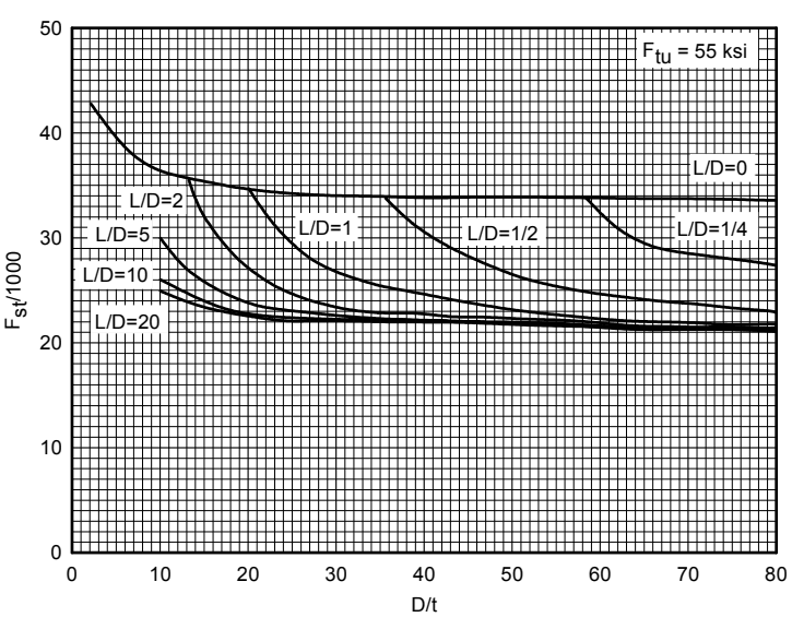
Figure description:
Fst/1000 vs D/t for Ftu = 55 ksi
Legend
- L/D=0 — color: black; symbol: solid line
- L/D=1/4 — color: black; symbol: solid line
- L/D=1/2 — color: black; symbol: solid line
- L/D=1 — color: black; symbol: solid line
- L/D=2 — color: black; symbol: solid line
- L/D=5 — color: black; symbol: solid line
- L/D=10 — color: black; symbol: solid line
- L/D=20 — color: black; symbol: solid line
Annotations
- Ftu = 55 ksi (text_label - position: top right corner)
| D/t | L/D=0 | L/D=1/4 | L/D=1/2 | L/D=1 | L/D=2 | L/D=5 | L/D=10 | L/D=20 |
|---|---|---|---|---|---|---|---|---|
| 2 | 43.0 | |||||||
| 4 | 41.0 | |||||||
| 6 | 39.0 | |||||||
| 8 | 37.5 | |||||||
| 10 | 36.5 | 30.0 | 26.0 | 25.0 | ||||
| 12 | 35.8 | 28.5 | 25.2 | 24.4 | ||||
| 13.5 | 35.5 | 35.5 | ||||||
| 14 | 35.4 | 35.0 | 27.2 | 24.5 | 24.0 | |||
| 16 | 35.2 | 31.8 | 25.5 | 23.8 | 23.4 | |||
| 20 | 34.6 | 34.6 | 28.5 | 24.0 | 23.2 | 22.8 | ||
| 25 | 33.8 | 31.5 | 26.0 | 23.2 | 22.8 | 22.4 | ||
| 30 | 33.8 | 28.5 | 24.5 | 22.8 | 22.4 | 22.2 | ||
| 35 | 33.8 | 33.8 | 27.0 | 23.8 | 22.6 | 22.2 | 22.0 | |
| 40 | 33.8 | 31.5 | 25.5 | 23.2 | 22.4 | 22.0 | 21.8 | |
| 50 | 33.8 | 28.0 | 24.5 | 22.5 | 22.2 | 21.8 | 21.6 | |
| 58 | 33.8 | 33.8 | ||||||
| 60 | 33.8 | 32.5 | 26.0 | 23.5 | 22.0 | 21.8 | 21.6 | 21.4 |
| 70 | 33.8 | 29.2 | 24.5 | 22.8 | 21.6 | 21.4 | 21.2 | 21.0 |
| 80 | 33.8 | 27.5 | 23.5 | 22.2 | 21.4 | 21.2 | 21.1 | 21.0 |
Notes: The chart displays the relationship between Fst/1000 and the ratio D/t for various L/D values ranging from 0 to 20. Ftu is a constant at 55 ksi.
Figure 2.8.3.2(a). Torsional modulus of rupture—plain carbon steels F tu = 55 ksi.
MIL-HDBK-5J
2.8.3.2
Lee, L.H.N., and Ades, C. S., "Plastic Torsional Buckling Strength of Cylinders Including the Effects of Imperfections," Journal of the Aeronautical Sciences, Vol. 24, No. 4, pp 241-248 (April 1957).