Both Figures 9.4 and 9.5 show the connection configured with continuity plates where required. The use of continuity plates is dictated by the need to satisfy prescribed limit states for the flange and web of the column. In a bolted connection, the configuration of the fasteners can impede the ability of the continuity plates to effectively address these limit states. The design intent for the CBB is to satisfy the prescribed limit states without continuity plates. In tests of wide-flange columns without continuity plates, the absence of the continuity plates did not appear to promote local flange bending or lead to other detrimental effects (Adan and Gibb, 2009). However, in the absence of additional tests, the need for continuity plates must be checked for all connections according to Step 17 of the design procedure.
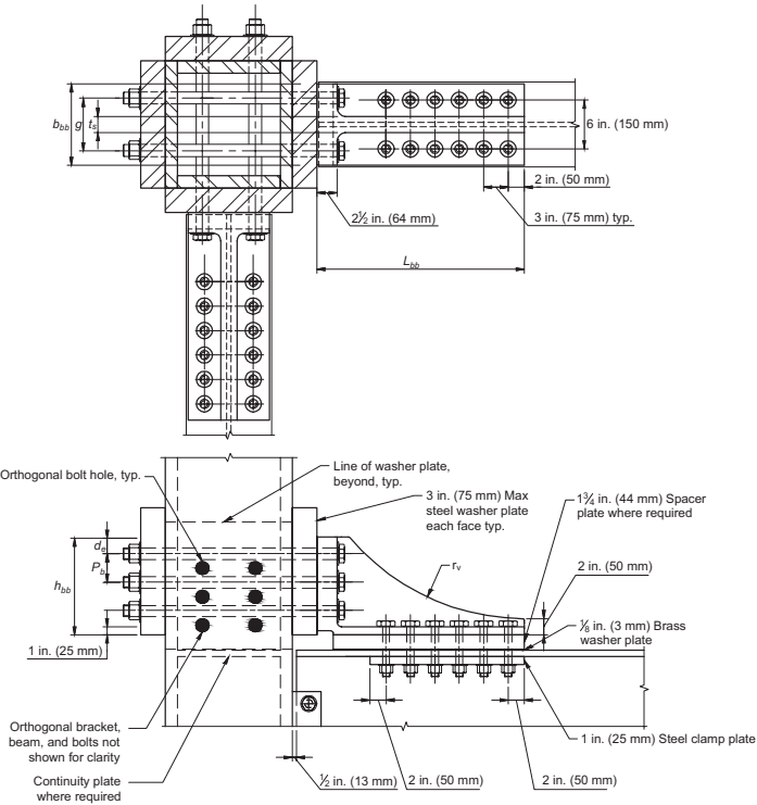
Figure description:
Entity: Box Column Connection Detailing for ConneXion (CBB
Key Components & Dimensions:
- Column: Box column configuration with optional internal continuity plates.
- Bracket: Side-mounted brackets bolted to the column and beam flange.
- : Length of the bracket.
- : Width of the bracket.
- : Height of the bracket.
- Fasteners: High-strength bolts with specific spacing:
- Horizontal bolt spacing: 3 in. (75 mm typical; 2 in. (50 mm edge distance.
- Vertical bolt spacing: (pitch; (edge distance.
- Plates & Washers:
- Steel Washer Plate: 3 in. (75 mm maximum width on each column face.
- Spacer Plate: in. (44 mm thick where required.
- Brass Washer Plate: in. (3 mm thick.
- Steel Clamp Plate: 1 in. (25 mm thick.
- Clearances:
- 1 in. (25 mm bottom bracket clearance.
- in. (13 mm gap between bracket and column face.
- Detailing Notes: Orthogonal bolt holes and brackets are noted but partially omitted for clarity; includes radius on the bracket profile.
Fig. C-9.1. Box column connection detailing for CBB.