6.6.1 Gage
The gage, , is as defined in Figures 6.2 through 6.4. The maximum gage dimension is limited to the width of the connected beam flange.
6.6.2 Pitch and Row Spacing
The minimum pitch distance is the bolt diameter plus in. (13 mm) for bolts up to 1 in. (25 mm) diameter and the bolt diameter plus in. (19 mm) for larger diameter bolts. The pitch distances, and , are the distances from the face of the beam flange to the centerline of the nearer bolt row, as shown in Figures 6.2 through 6.4 . The pitch distances, and , are the distances from the face of the continuity plate to the centerline of the nearer bolt row, as shown in Figures 6.2 through 6.4 .
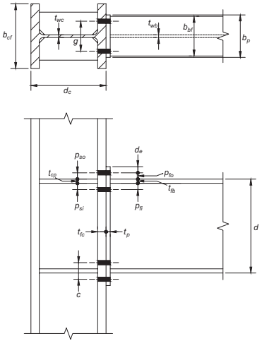
Figure description:
Four-bolt unstiffened extended end-plate (4E geometry
The image provides technical drawings (top and side views of a beam-to-column connection with the following key parameters:
- Column Dimensions:
- : Width of column flange
- : Thickness of column web
- : Depth of column
- : Thickness of column flange
- : Thickness of continuity plate
- Beam Dimensions:
- : Width of beam flange
- : Thickness of beam web
- : Depth of beam
- : Thickness of beam flange
- End-Plate Dimensions:
- : Width of end-plate
- : Thickness of end-plate
- Bolt Layout and Spacing:
- : Horizontal bolt gauge
- : Bolt edge distance from end-plate top
- : Vertical distance from beam flange outer face to outer bolt row
- : Vertical distance from beam flange inner face to inner bolt row
- : Column-side bolt pitch distances relative to continuity plates
- : Vertical bolt spacing at the bottom flange extension
Fig. 6.2. Four-bolt unstiffened extended end-plate (4E) geometry.
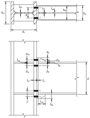
Figure description:
The image illustrates the geometric parameters for four-bolt extended end-plate beam-to-column connections (4E and 4ES.
Key Entities and Dimensions:
- Column Parameters:
- : Column flange width
- : Column depth
- : Column web thickness
- : Column flange thickness
- : Continuity plate thickness
- Beam Parameters:
- : Beam flange width
- : Beam depth
- : Beam web thickness
- : Beam flange thickness
- End-Plate and Bolt Parameters:
- : End-plate width
- : End-plate thickness
- : Bolt gauge (horizontal spacing
- , : Bolt pitch (vertical distance from flange face to outer and inner bolts
- : Edge distance from bolt to end-plate edge
- , : Pitch for bolts relative to continuity plates
- : Vertical bolt spacing
- Stiffener Parameters (for 4ES:
- : Stiffener length
- : Stiffener height
- : Stiffener thickness
Fig. 6.3. Four-bolt stiffened extended end-plate (4ES) geometry.
The spacing, , is the distance between the inner and outer row of bolts in an 8ES end-plate moment connection and is shown in Figure 6.4. The spacing of the bolt rows shall be at least times the bolt diameter.
User Note: A distance of 3 times the bolt diameter is preferred. The distance must be sufficient to provide clearance for any welds in the region.
6.6.3 End-Plate Width
The width of the end plate shall be greater than or equal to the connected beam flange width. The effective end-plate width shall not be taken greater than the connected beam flange plus 1 in. (25 mm).
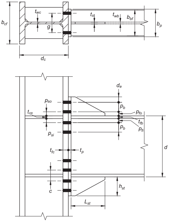
Figure description:
Key Entities and Details
- Connection Type: Eight-bolt stiffened extended end-plate (8ES moment connection between a beam and a column.
- Primary Components:
- Column: I-shaped section with flange width , depth , web thickness , and flange thickness . Includes continuity plates of thickness .
- Beam: I-shaped section with flange width , depth , web thickness , and flange thickness .
- End Plate: Attached to the beam end with width and thickness .
- Stiffeners: Triangular plates reinforcing the extended end plate with thickness , length , and height .
- Fasteners: Eight bolts arranged in four rows.
- Geometric Parameters:
- Transverse: Bolt gauge .
- Vertical Bolt Spacing/Pitch: Exterior stiffener bolts (, interior stiffener bolts (, exterior flange bolts (, interior flange bolts (, and general pitch .
- Edge Distance: Distance from the outer bolt to the end plate edge (.
- Clearances: Vertical clear distance at the interior bolt rows.
Fig. 6.4. Eight-bolt stiffened extended end-plate (8ES) geometry.
6.6.4 End-Plate Stiffener
The two extended stiffened end-plate connections, Figures 6.1(b) and (c), require a stiffener welded between the connected beam flange and the end plate. The minimum stiffener length, , shall be
(6.6-1)
where is the height of the stiffener, equal to the height of the end plate from the outside face of the beam flange to the end of the end plate as shown in Figure 6.5.
The stiffener plates shall be terminated at the beam flange and at the end of the end plate with landings not less than 1 in. (25 mm) long. The stiffener shall be clipped where it meets the beam flange and end plate to provide clearance between the stiffener and the beam flange weld.
When the beam and end-plate stiffeners have the same material strengths, the thickness of the stiffeners shall be greater than or equal to the beam web thickness. If the beam and end-plate stiffener have different material strengths, the thickness of the stiffener shall not be less than the ratio of the beam-to-stiffener plate material yield stresses times the beam web thickness.
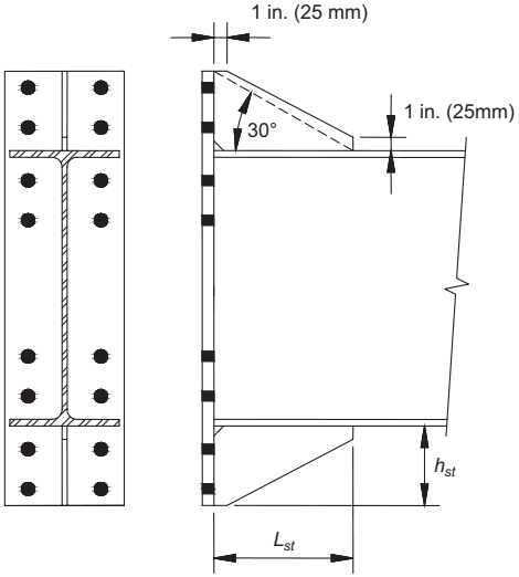
Figure description:
Key Information: End-Plate Stiffener Layout (8ES
- Entities: Structural beam (I-beam, end-plate, and stiffener plates (top and bottom.
- Geometry & Dimensions:
- Stiffener Angle: 30° from the beam flange.
- Top Setbacks: 1 in. (25 mm from the end-plate and 1 in. (25 mm from the beam flange.
- Bottom Parameters: (length of stiffener and (height of stiffener.
- Bolt Configuration: 8-bolt stiffened (8ES pattern shown in the front view.
- Design Note: Stiffener thickness must be beam web thickness (adjusted by yield stress ratio if materials differ.
Fig. 6.5. End-plate stiffener layout and geometry for 8ES. Geometry for 4ES similar.
6.6.5 Finger Shims
The use of finger shims (illustrated in Figure 6.6) at the top and/or bottom of the connection and on either or both sides is permitted, subject to the limitations of the RCSC Specification.
6.6.6 Welding Details
Welding of the beam to the end plate shall conform to the following limitations:
- (1) Weld access holes shall not be used.
- (2) The beam flange to end-plate joint shall be made using a CJP groove weld without backing. The CJP groove weld shall be made such that the root of the weld is on the beam web side of the flange. The inside face of the flange shall have a 5/16 in. (8 mm) fillet weld. These welds shall be demand critical.
- (3) For stiffened end-plate connections, the beam flange-to-end-plate weld shall be made before the stiffener is installed.
- (4) The beam web-to-end-plate joint shall be made using either fillet welds or CJP groove welds. When used, the fillet welds shall be sized to develop the full
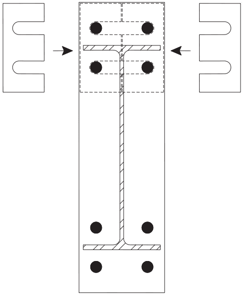
Figure description:
- Entities: Finger shims, I-beam (structural member, bolt holes, and connection plate.
- Function: Demonstrates the lateral insertion of slotted finger shims into a bolted structural connection.
- Key Details:
- Two E-shaped finger shims are positioned to slide around bolts via horizontal slots.
- Arrows indicate inward insertion direction towards the web of the I-beam.
- Dotted lines show the intended final position of the shims within the connection assembly.
- The connection features a vertical arrangement of four bolts on the top section and four on the bottom section.
Fig. 6.6. Typical use offinger shims.
strength of the beam web in tension from the inside face of the flange to 6 in. (150 mm) beyond the bolt row farthest from the beam flange.
- (5) Backgouging of the root is not required in the flange directly above and below the beam web for a length equal to 1.5k₁. A full-depth PJP groove weld shall be permitted at this location.
- (6) When used, all end-plate-to-stiffener joints shall be made using CJP groove welds.
Exception: When the stiffener is ³/₈ in. (10 mm) thick or less, it is permitted to use fillet welds that develop the strength of the stiffener.