Step 1. Compute the probable maximum moment at the location of the plastic hinge, , in accordance with Section 2.4.3, where = plastic section modulus of the beam.
Step 2. Select a trial bracket from Table 9.1.
Step 3. Determine the distance of the plastic hinge from the face of column, .
per Table 9.1, in. (mm)
Step 4. Compute the shear force at the plastic hinge, , in accordance with Section 2.4.4.
Step 5. Compute the probable maximum moment at the face of the column, , in accordance with Section 2.4.5.
Step 6. Compute the required column bolt tensile strength, :
(9.7-1)
where
effective beam depth, calculated as the centroidal distance between bolt groups in the upper and lower brackets, in. (mm)
number of column bolts per Table 9.1
Step 7. Check the design tensile strength of the column bolts:
(9.7-2)
where
bolt nominal cross-sectional area, in.
nominal tensile strength of bolt from the AISC Specification, ksi (MPa)
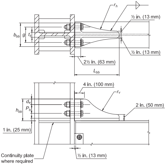
Figure description:
Fig. 9.4. W-series Connection Detailing
Key Components and Dimensions:
- Entities: Structural steel W-series beam connection, column section, bolted connection plates, and weld symbols.
- Horizontal Detailing (Top View:
- : Total width of the bracket base.
- : Gauge distance between bolts.
- : Thickness of the central stiffener/plate.
- : Horizontal radius of the bracket profile.
- : Total length of the bracket.
- Fixed Offsets: in. (63 mm from the face to the first bolt; in. (13 mm tip thickness.
- Vertical Detailing (Side View:
- : Total height of the bracket.
- : Edge distance for bolts.
- : Pitch between bolts.
- : Vertical radius of the bracket profile.
- Fixed Offsets: 4 in. (100 mm flat top length; 2 in. (50 mm bracket end height; 1 in. (25 mm bottom clearance; in. (13 mm weld/plate setback.
- Structural Features: Includes a continuity plate where required within the column web.
Fig. 9.4. W-series connection detailing.
| Bracket Designation | Bracket Length, | Bracket Height, | Bracket Width, | Number of Column Bolts, | Column Bolt Gage, | Column Bolt Diameter, |
|---|---|---|---|---|---|---|
| Lbb in. (mm) | hbb in. (mm) | bbb in. (mm) | ncb | g in. (mm) | in. (mm) | |
| W3.0 | 16 (400) | 5½ (140) | 9 (230) | 2 | 5½ (140) | 1⅜ (35) |
| W3.1 | 16 (400) | 5½ (140) | 9 (230) | 2 | 5½ (140) | 1½ (38) |
| W2.0 | 16 (400) | 8¾ (220) | 9½ (240) | 4 | 6 (150) | 1⅜ (35) |
| W2.1 | 18 (450) | 8¾ (220) | 9½ (240) | 4 | 6½ (160) | 1½ (38) |
| W1.0 | 25½ (640) | 12 (300) | 9½ (240) | 6 | 6½ (160) | 1½ (38) |
| B2.1 | 18 (450) | 8¾ (220) | 10 (250) | 4 | 6½ (160) | 1½ (38) |
| B1.0 | 25½ (640) | 12 (300) | 10 (250) | 6 | 6½ (160) | 1½ (38) |
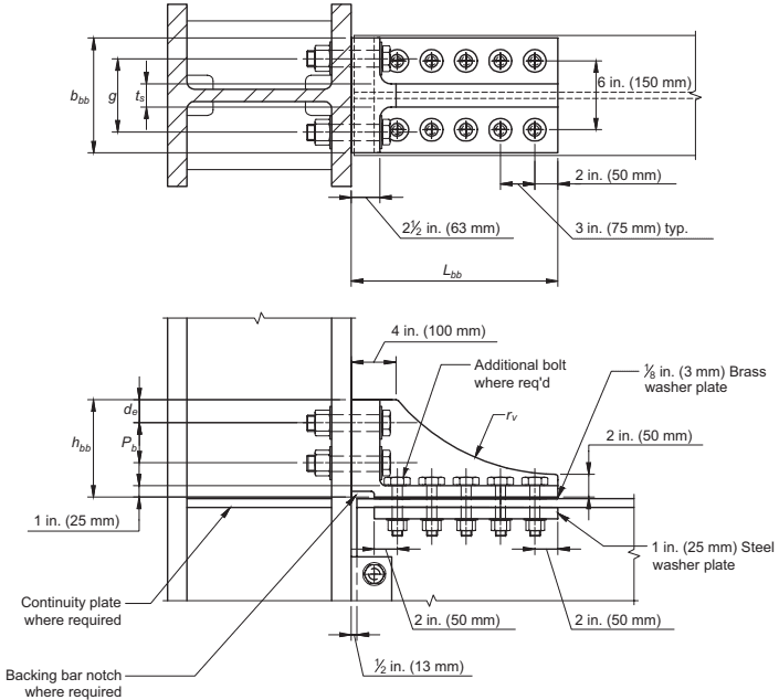
Figure description:
Entities and Components:
- B-series Connection: A structural steel connection joining a beam to a column flange using bolts and plates.
- Beam/Column Interface: Includes a backing bar notch and optional continuity plates.
- Fasteners: Rows of bolts securing the connection plates to the beam web and flange.
- Washers: Includes 1/8 in. (3 mm Brass washer plates and 1 in. (25 mm Steel washer plates.
Key Dimensions and Specifications:
- Horizontal Spacing: Bolt spacing is 3 in. (75 mm typical, with a 2 in. (50 mm end distance.
- Vertical Spacing: 6 in. (150 mm between bolt rows on the beam web.
- Plate Dimensions: (length, (width, (height, (thickness, and (gauge.
- Clearances: 1 in. (25 mm gap for continuity plates; 4 in. (100 mm top plate set-back; in. (63 mm from column face to first bolt row.
- Additional Hardware: "Additional bolt where req'd" noted on the vertical leg of the connection; radius indicated for the gusset plate.
Fig. 9.5. B-series connection detailing.
| Bracket Designation | Column Bolt Edge Distance, de | Column Bolt Pitch, pb | Bracket Stiffener Thickness, ts | Bracket Stiffener Radius, rv | Bracket Horizontal Radius, rh | Minimum Fillet Weld Size, w |
|---|---|---|---|---|---|---|
| in. (mm) | in. (mm) | in. (mm) | in. (mm) | in. (mm) | in. (mm) | |
| W3.0 | 2½ (63) | n.a. | 1 (25) | n.a. | 28 (700) | ½ (13) |
| W3.1 | 2½ (63) | n.a. | 1 (25) | n.a. | 28 (700) | ⅝ (16) |
| W2.0 | 2¼ (56) | 3½ (88) | 2 (50) | 12 (300) | 28 (700) | ¾ (19) |
| W2.1 | 2¼ (56) | 3½ (88) | 2 (50) | 16 (400) | 38 (950) | ⅞ (22) |
| W1.0 | 2 (50) | 3½ (88) | 2 (50) | 28 (700) | n.a. | ⅞ (22) |
| Bracket Designation | Column Bolt Edge Distance, de in. (mm) | Column Bolt Pitch, pb in. (mm) | Bracket Stiffener Thickness, ts in. (mm) | Bracket Stiffener Radius, rv in. (mm) | Number of Beam Bolts, nbb | Beam Bolt Diameter, in. (mm) |
|---|---|---|---|---|---|---|
| B2.1 | 2 (50) | 3½ (88) | 2 (50) | 16 (400) | 8 or 10 | 1⅛ (28) |
| B1.0 | 2 (50) | 3½ (88) | 2 (50) | 28 (700) | 12 | 1⅛ (28) |
Step 8. Determine the minimum column flange width to prevent flange tensile rupture:
(9.7-3)
(9.7-3M)
where
- specified minimum tensile strength of flange material, ksi (MPa)
- specified minimum yield stress of flange material, ksi (MPa)
- ratio of expected tensile strength to specified minimum tensile strength for flange material
- ratio of expected yield stress to specified minimum yield stress for flange material
- width of column flange, in. (mm)
- = diameter of column flange bolts, in. (mm)
Step 9. Check the column flange for flexural yielding:
(9.7-4)
where
User Note: The simplified column flange yield line mechanism parameters, , assume there are no continuity plates. If continuity plates are provided, the minimum column flange thickness from Equation 9.7-4 is conservative. Alternatively, when continuity plates are provided, new values of can be derived to justify a smaller column flange thickness.
The simplified column flange yield line mechanism parameters, , also assume that the distance from the top-most bolt line to the top of the column is at least equal to where column flange width, in. (mm) and column bolt gage, in. (mm) as specified in Table 9.1.
Step 10. If the bracket is welded to the beam flange, proceed to Step 14; otherwise, check beam flange tensile rupture. To preclude a net section rupture of the beam flange, the net section of the beam section shall satisfy the following:
(9.7-5)
where
= specified minimum tensile strength of beam, ksi (MPa) = specified minimum yield stress of beam, ksi (MPa) = ratio of expected tensile strength to specified minimum tensile strength = ratio of expected yield stress to specified minimum yield stress = plastic section modulus of beam, = plastic section modulus of net section of the beam at location of the plastic hinge,
User Note: of the beam may be computed by accounting for only the holes in the tension flange, or more simply, of the beam may be computed by accounting for the holes in both flanges. Note that if the former approach is employed, the plastic neutral axis will not be at the mid-depth of the beam. If the latter approach is employed, can be computed as follows:
(9.7-6) (9.7-6M)
where
Step 11. Compute the beam flange force, :
(9.7-7)
Step 12. Check beam bolt strength:
(9.7-8)
where
- nominal shear stress of bolt from the AISC Specification, ksi (MPa)
- = clear distance, in the direction of the force, between the edge of the hole and the edge of the adjacent hole or edge of beam flange, in. (mm)
- = thickness of beam flange, in. (mm)
Step 13. Check the beam flange for block shear rupture:
(9.7-10)
where is as defined in the block shear rupture provisions of AISC Specification Section J4.3.
Step 14. If the bracket is welded to the beam flange, determine the required size of the fillet weld.
(9.7-11)
where
= filler metal classification strength, ksi (MPa) = 0.60 = length of available fillet weld, in. (mm) = in. - l) (9.7-12) = mm - l) (9.7-12M)
where
bracket length per Table 9.3, in. (mm)
- = bracket overlap distance, in. (mm)
- if
- in. ( 125 mm ) if
- = fillet weld size (not less than minimum fillet weld size specified in Table 9.2), in. (mm)
Step 15. Check design shear strength of beam in accordance with the AISC Specification.
The required shear strength of the beam shall be determined in accordance with Section 2.5.
Step 16. Design the beam web-to-column connection.
The required shear strength of the beam web-to-column connection shall be taken equal to the required shear strength of the beam.
The beam web-to-column connection shall be a single-plate shear connection meeting the requirements of the AISC Specification.
The single-plate shear connection shall be connected to the column flange using a two-sided fillet weld, two-sided PJP groove weld, or CJP groove weld.
Step 17. Check the continuity plate requirements in accordance with Section 2.6 using the flange force computed in Step 11.
User Note: When checking column flange continuity plate requirements, only the limit states of web local yielding and web local crippling need be considered. The limit state of flange local bending need not be considered because satisfying Equation 9.7-4 precludes flange local bending failure.
Step 18. Check the column panel zone in accordance with Section 2.7.
When computing the required panel-zone shear strength, the depth of the panel zone shall be taken as , as defined in Step 6.
Step 19. Check the column-beam moment ratio in accordance with Section 2.8.
Step 20. If the column is a box configuration, determine the size of the steel washer plate between the column flange and the bracket such that
where