Beam flange continuity plates serve several purposes in moment connections. They help to distribute beam flange forces to the column web, stiffen the column web to prevent local crippling and yielding, and limit local flange bending under the concentrated beam-flange forces. Continuity plates also reduce stress concentrations that can occur in the joint between the beam flange and column due to nonuniform stiffness of the attached elements. Unless otherwise specified in the standard, continuity plates for prequalified connections follow the requirements of the AISCE Seismic Provisions [Section E2.6f for intermediate moment frames (IMF) and Section E3.6f for special moment frames (SMF)]. The continuity plate requirements in the AISCE Seismic Provisions are primarily applicable for an I-shaped beam connected to the flange of an I-shaped column.
No criteria for continuity plates are provided for built-up box columns in the AISC Seismic Provisions or in the standard, as there is insufficient research available at present to support definitive design criteria. As such, it is recommended that continuity plates, also referred to as diaphragm plates when used in box columns, be
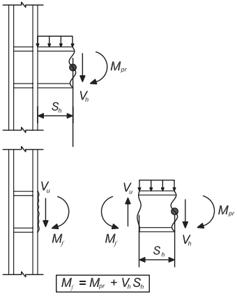
Figure description:
Fig. C-2.4. Free-body diagram for determination of
Key Entities and Variables:
- : Moment at the face of the column.
- : Probable maximum moment at the plastic hinge.
- : Shear force at the plastic hinge.
- : Distance from the column face to the plastic hinge.
- : Shear force at the column face.
- Components: Steel column with continuity plates and a beam segment undergoing plastic deformation.
Governing Equation:
Fig. C-2.4. Free-body diagram for determination of Mf.
provided for built-up box columns unless justified otherwise by testing or analysis. During fabrication of built-up box columns, a continuity plate can be welded to three sides when the box is still open. The weld between the continuity plate and the closing side of the box column is normally made using the electro-slag welding (ESW) process. Tests have shown that premature fractures can occur at the ESW weld due to a notch condition introduced by the containment plates of the ESW weld (Lee et al., 2014). In cases where moment frame beams do not connect to all four sides of the box column, it is recommended that the ESW side of the column be located where there is no moment frame beam. Other suggestions to mitigate brittle fracture are provided by Lee et al. (2014).
When beams are moment connected to the side plates of boxed wide-flange column sections, continuity plates should be provided opposite the beam flanges unless justified otherwise by testing or analysis.
Almost all connection assembly testing has been conducted on specimens that include a significant length (typically one-half story height) of column above and below the beam or beams framing into the column. Thus, the condition that typically exists in a structure’s top story, where the column terminates at the level of the beam top flange, has not specifically been tested to demonstrate acceptable detailing. A cap plate detail similar to that illustrated in Figure C-2.5 is believed to be capable of providing reliable performance when connection elements do not extend above the beam top flange. In some connections—for example, extended end-plate and cast
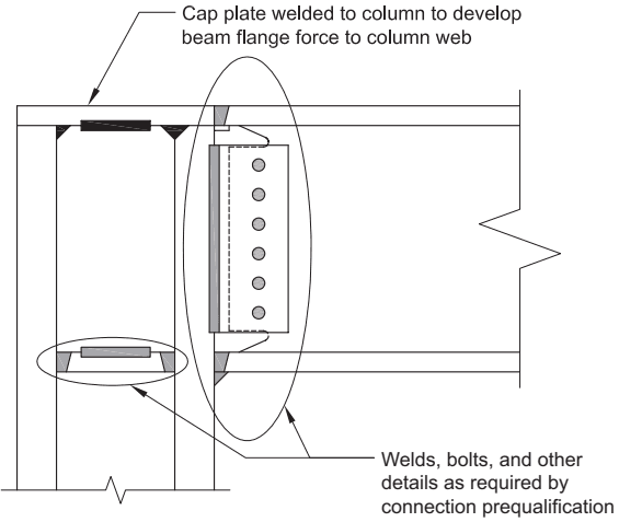
Figure description:
Image Detail: Cap plate detail at column top for RBS connection
- Cap Plate: Welded to the top of the column to transfer beam flange forces directly to the column web.
- Application: Used for top-story configurations where the column terminates at the beam's top flange level.
- Connection Components: Includes a combination of welds, bolts, and shear plates as specified by connection prequalification standards.
- Purpose: Provides a reliable load path in the absence of a column extension above the beam framing level.
Fig. C-2.5. Example cap plate detail at column top for RBS connection.
bolted bracket connections, portions of the connection assembly extend above the column top flange. In such cases, the column should be extended to a sufficient height above the beam flange to accommodate attachment and landing of those connection elements. The continuity plates should be placed opposite the beam top flange, as is done at intermediate framing levels.