Step 1. Compute the probable maximum moment at the plastic hinge, , in accordance with Section 2.4.3, where plastic section modulus of the beam.
Step 2. Check beam flange tensile rupture. To preclude a net section fracture of the beam flange, the net section of the beam section shall satisfy the following:
(13.5-1)
where
- specified minimum tensile strength of beam, ksi (MPa)
- = specified minimum yield stress of beam, ksi (MPa)
- = ratio of expected yield stress to specified minimum yield stress
- plastic section modulus of net section of the beam at location of the plastic hinge, in.
User Note: of the beam may be computed by accounting for only the holes in the tension flange or, more simply, of the beam may be computed by accounting for the holes in both flanges. Note that if the former approach is employed, the plastic neutral axis will not be at the mid-depth of the beam, which complicates the calculations somewhat. If the latter approach is employed, the calculations are a bit simpler and the requirement of Equations 13.5-1 may be met with a maximum shear bolt-hole diameter that is determined by:
(13.5-2)
(13.5-2M)
where
After the maximum shear bolt hole diameter is determined, the maximum shear bolt diameter can be determined from AISC Specification Table J3.3 or Table J3.3M.
Step 3. Determine the design shear strength per shear bolt based on the limit states of shear fracture and material bearing as follows:
where
- gross area of a shear bolt measured through its shank, in.
nominal shear stress of a bolt from the AISC Specification, ksi (MPa)
Step 4. Estimate the number of shear bolts, , required in each beam flange as follows:
(13.5-4)
where is an even integer.
Step 5. Determine the distance of the plastic hinge from the face of the column, , based on the estimated number of shear bolts, the horizontal end distance, and bolt spacing.
(13.5-5)
where
S1 = distance between the face of the column and the first row of shear bolts, in. (mm)
spacing of the shear bolts, in. (mm)
Step 6. Compute the shear force at the plastic hinge, , in accordance with Section 2.4.4.
Step 7. Compute the probable maximum moment at the face of the column, , in accordance with Section 2.4.5.
Step 8. Compute the probable force in the T-stub, , due to :
(13.5-7)
where is used to estimate the sum of the depth of the beam and the thickness of the T-stem.
Step 9. Determine the size of the T-stem required. The stem thickness shall be determined based on the limit states of gross section yielding and net section fracture (checked in this step) and compression due to flexural buckling (checked in Step 16).
In sizing the T-stem, the Whitmore width, , shall be taken as
(13.5-8)
where
gage of shear bolts in the T-stub, in. (mm)
The minimum stem thickness, , based on yielding of the T-stem is
(13.5-9)
where
specified minimum yield stress of the T-stub, ksi (MPa)
width of the T-stub measured parallel to the column flange width, in. (mm)
The minimum stem thickness, , based on fracture of the T-stem is:
(13.5-10)
(13.5-10M)
where
Fut = specified minimum tensile stress of T-stub, ksi (MPa) dvht = diameter of the holes in the T-stem for the shear bolts, in. (mm)
To ensure that compression buckling of the T-stem will not control, select the thick- ness of the T-stem such that
(13.5-11)
where
Step 10. Determine the size of the bolts connecting the T-stub to the column flange. The minimum diameter of the tension bolts, , shall be determined as
(13.5-12)
where
Step 11. Determine the preliminary configuration of the T-flange. The flange width of the T-stub, , shall be computed as
(13.5-13)
where
User Note: The limit of in Equation 13.5-14 is a computation limit only and is not a physical limitation on the dimension . The dimension may be estimated as for preliminary estimation of prying forces.
The design strength of a single tension bolt, , shall be computed as
(13.5-15)
where
gross area of a tension bolt measured through its shank, in.
The required T-flange strength, , in units of kips per tension bolt (N per tension bolt) shall be computed as
(13.5-16)
The minimum flange thickness, tft, based on a mixed-mode failure, which will typi- cally govern, shall be computed as:
(13.5-17)
where (13.5-18) (13.5-19) (13.5-20)
In certain situations, the term under the radical in Equation 13.5-17 can be negative, resulting in an erroneous required flange thickness. An alternate formulation of Equation 13.5-17 that can be applied in these cases is
(13.5-21)
where (13.5-22)
User Note: In all cases, the flange thickness required to eliminate prying action can be computed as: (13.5-23)
Step 12. Select a W-shape from which the T-stubs will be cut based on the following:
- The minimum depth required to accommodate the setback and horizontal end distance of the beam, , and the length of the shear-bolt group, , found in Step 5.
- The minimum web thickness, , found in Step 9.
- The minimum flange width, , and flange thickness, , found in Step 11.
Step 13. Check the connection rotational stiffness to ensure that the connection is classified as fully restrained. The following shall be satisfied:
where
| Ibeam | = strong axis moment of inertia of the beam, in.4 (mm4) | |
| Lo | = theoretical length of the connected beam measured between the working points of the adjacent columns, in. (mm) | |
| Ki | = db2 Kten Kcomp ———————— Kten + Kcomp | (13.5-25) |
| Kten | = ( 1/Kflange + 1/Kstem + 1/Kslip )-1 | (13.5-26) |
| Kcomp | = ( 1/Kstem + 1/Kslip )-1 | (13.5-27) |
| Kflange | = 12ntb EIft (α'βa + 3b'βb) —————————————————— b'3βb (4α'βa + 3b'βb) | (13.5-28) |
| Kstem | = tst E (WT - bfb)2 —————————————————— Lstem [ (WT - bfb) + bfb ln ( bfb/WT ) ] | (13.5-29) |
and
| Lstem = length of stem, in. (mm) | |
| Kslip = Pslip — Δslip | (13.5-30) |
| Pslip = nvb α (0.70Fnt Avb)μ | (13.5-31) |
where
| α | = 1.00 for ASTM F3125/F3125M Grades A325, A325M, and F1852 bolts = 0.88 for ASTM F3125/F3125M Grades A490, A490M, and F2280 bolts | |
| Ift | = p tft3 / 12 | (13.5-32) |
| βa | = 1 + 12 E Ift / (G p tft a'2) | (13.5-33) |
| βb | = 1 + 12 E Ift / (G p tft b'2) | (13.5-34) |
| Δslip | = 0.0076 in. (0.19 mm) | (13.5-35) |
Step 14. Compute the maximum force in the T-stub due to . Using the actual T-stem thickness, the actual flange force that is to be carried by the T-stubs, , shall be computed as follows:
(13.5-36)
Step 15. Back-check the strength of the shear bolts with the actual flange force. Use from Step 3 to confirm that the number of shear bolts, , estimated in Step 4 is adequate to resist the actual flange force, .
(13.5-37)
Step 16. Back-check the strength of the T-stem using the maximum beam flange force. Back-check that the gross section yielding, net section fracture, and flexural buckling strengths of the T-stem are adequate to resist the maximum flange force, .
For stem gross section yielding
(13.5-38)
For stem net section fracture
For stem flexural buckling
(13.5-40)
If , then
If , then is determined using the provisions in AISC Specification Section E3 using as determined previously and taking equal to .
Step 17. Back-check the flange strength of the T-stub. The flange strength of the T-stub shall be computed as follows:
(13.5-42)
where is the minimum of (plastic flange mechanism), (mixed-mode failure), and (tension bolt fracture with no prying), as computed in the following.
For the limit state of a plastic mechanism in the tension flange, the design strength per tension bolt shall be calculated as follows:
(13.5-43)
For the limit state of tension flange yielding followed by fracture of the bolts (a mixed-mode failure), the design strength per tension bolt shall be calculated as follows:
(13.5-44)
For the limit state of bolt fracture without yielding of the tension flange, the design strength per tension bolt shall be calculated as follows:
| φT3 = φrnt | (13.5-45) | |
| where | ||
| a′ | = a + 1/2dtb | (13.5-46) |
| a | = 1/2(bft − gtb) ≤ 1.25b | (13.5-47) |
| b′ | = b − 1/2dtb | (13.5-48) |
| b | = 1/2(gtb − tst,eff) | (13.5-49) |
| p | = 2WT / ntb | (13.5-50) |
| tst,eff | = k1 + tst / 2 | (13.5-51) |
| δ | = 1 − dtht / p | (13.5-52) |
| dtht | = diameter or width of holes in T-flange for the tension bolts, in. (mm) |
= diameter or width of holes in T-flange for the tension bolts, in. (mm)
Step 18. Check the bearing and tear-out strength of the beam flange and T-stem. Bearing and tearout of the shear bolts shall be checked in a manner consistent with AISC Specification Chapter J. For these calculations, bearing and tearout are considered to be ductile failure modes.
Step 19. Check block shear of the beam flange and the T-stem. Block shear of the T-stem and beam flange shall be checked in a manner consistent with AISC Specification Chapter J. For the purpose of this design, the block shear failure shall be considered a ductile failure mode and shall be used.
The alternate block shear mechanism illustrated in Figure 13.7 need not be checked.
Step 20. Check design shear strength of beam in accordance with the AISC Specification.
The required shear strength of the beam shall be determined in accordance with Section 2.5.
Step 21. Design the beam web-to-column connection.
The beam web-to-column connection shall be a single-plate shear connection meeting the requirements of the AISC Specification.
The required shear strength of the single-plate connection shall be taken equal to the required shear strength of the beam.
User Note: Because of the large setback required, the shear connection may need to be designed as an extended single-plate shear connection. Most importantly, the length of the shear connection, , should be determined so as to fit between the flanges of the T-stubs allowing ample clearance.
Step 22. Check the column flange for flexural yielding (see Figure 13.8):
The column flange flexural design strength is
(13.5-53)
where
specified minimum yield stress of column flange material, ksi (MPa)
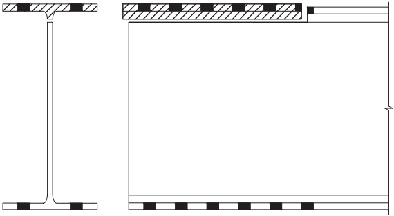
Figure description:
- Image Type: Technical engineering diagram (Figure 13.7.
- Subject: Alternate block shear mechanism in a structural steel connection.
- Key Entities:
- I-Beam/Column: Shown in cross-section (left and side elevation (right.
- Bolts: Represented by black squares along the top and bottom flanges.
- Shear Planes: Indicated by diagonal hatching patterns on the top flange connection area.
- Connection Plates: Components attached to the flanges of the main structural member.
Fig. 13.7. Alternate block shear mechanism.
Alternatively, the column flange thickness shall satisfy the following:
(13.5-59)
User Note: The presence of continuity plates stiffening the column flanges precludes the need to check prying forces resulting from column-flange deformations.
- Step 23. Check continuity plate requirements in accordance with Section 2.6.
- Step 24. Check the panel zone in accordance with Section 2.7.
- Step 25. Check the column-beam moment ratio in accordance with Section 2.8.
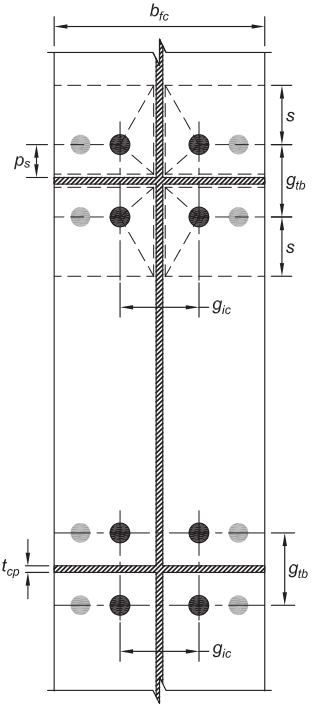
Figure description:
Fig. 13.8: Dimensions for yield-line analysis of column flange
- Subject: Structural engineering diagram of a column flange with bolt patterns and yield-line patterns (dashed lines.
- Key Geometric Parameters:
- : Width of the column flange.
- : Gauge distance between the inner column bolts.
- : Vertical distance between bolts across a transverse stiffener or plate.
- : Vertical distance from a bolt row to the boundary of a yield-line mechanism.
- : Vertical distance from a bolt row to a transverse stiffener.
- : Thickness of the transverse plate/stiffener.
- Key Components:
- Column Web: Represented by the central cross-hatched vertical line.
- Transverse Stiffeners: Horizontal cross-hatched sections intersecting the web.
- Bolts: Indicated by shaded circular icons arranged in patterns of four.
- Yield Lines: Dashed diagonal and horizontal lines indicating potential plastic failure mechanisms in the flange.
Fig. 13.8. Dimensions for yield-line analysis of column flange.