Step 1. Compute the probable maximum moment at the plastic hinge, , in accordance with Section 2.4.3, where plastic section modulus of the beam. The value of shall be taken equal to 1.4 .
User Note: The value of 1.4 for WUF-W moment connections is based on experimental data that shows a high degree of strain hardening.
Step 2. The plastic hinge location shall be taken to be at the face of the column; that is, .
Step 3. Compute the shear force at the plastic hinge, , in accordance with Section 2.4.4.
Step 4. Compute the probable maximum moment at the face of the column, , in accordance with Section 2.4.5.
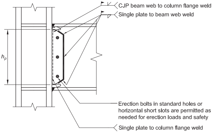
Figure description:
Fig. 8.2. General details of beam web-to-column flange connection
- Key Components:
- Beam and Column: Shows the intersection of a beam web and a column flange.
- Single Plate: Connects the beam web to the column flange.
- : Dimension indicating the height of the single plate.
- Weld Details:
- CJP beam web to column flange weld: Located at the top and bottom of the web connection area.
- Single plate to beam web weld: Fillet welds along the vertical and sloped edges of the plate.
- Single plate to column flange weld: Fillet weld at the interface of the plate and column.
- Fasteners:
- Erection bolts: Three bolts shown in standard holes or horizontal short slots for erection loads and safety.
Fig. 8.2. General details of beam web-to-column flange connection.
User Note: because is needed to check continuity plate requirements (Step 6), and panel zone requirements (Step 7).
Step 5. Check design shear strength of the beam according to the AISC Specification.
The required shear strength of the beam shall be determined in accordance with Section 2.5.
Step 6. Check continuity plate requirements in accordance with Section 2.6.
Step 7. Check the panel zone in accordance with Section 2.7.
Step 8. Check the column-beam moment ratio in accordance with Section 2.8.
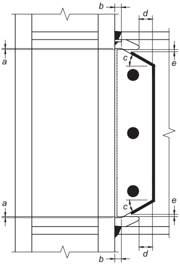
Figure description:
Key Entities
- Column: Vertical H-shaped structural member.
- Beam: Horizontal structural member connected to the column flange.
- Connection Plate (Shear Tab: Vertical plate with three bolts securing the beam web.
- Welds: Indicated by black triangles connecting structural components.
Dimensional Parameters
- a: Vertical clearance/alignment distance at the top and bottom column-beam interface.
- b: Horizontal weld/offset dimension at the connection point.
- c: Angle of the tapered chamfer on the top and bottom of the connection plate.
- d: Horizontal edge distance from the plate taper to the bolt line reference.
- e: Vertical gap/clearance at the top and bottom edges of the connection plate.
Notes
- a = ¼ in. (6 mm) minimum, ½ in. (13 mm) maximum
- c = 30° (±10°)
- in. (50 mm) minimum
- e = ½ in. (13 mm) minimum distance, 1 in. (25 mm) maximum distance from end of fillet weld to edge of access hole
Fig. 8.3. Details at top and bottom of single-plate shear connection.