Step 1. Choose trial values for the beam sections and column sections subject to the prequalification limits of Section 12.3 assuming fully restrained beam-to-column
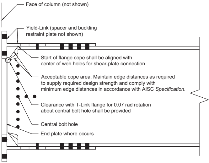
Figure description:
Subject: Technical diagram of beam coping details for a Yield-Link connection.
Key Components and Specifications:
- Yield-Link: Connection point between the beam and the face of the column (column not shown.
- Beam Coping:
- Alignment: Start of flange cope must align with the center of web holes for the shear-plate connection.
- Acceptable Cope Area: Must maintain required edge distances for design strength in compliance with AISC Specifications.
- Rotation Clearance: Clearance must be provided for 0.07 rad rotation about the central bolt hole relative to the T-Link flange.
- End Plate: Indicated at the vertical interface of the beam.
- Hardware: Multiple bolt holes are indicated on the beam web and flange connection plates.
(a) Beam coping
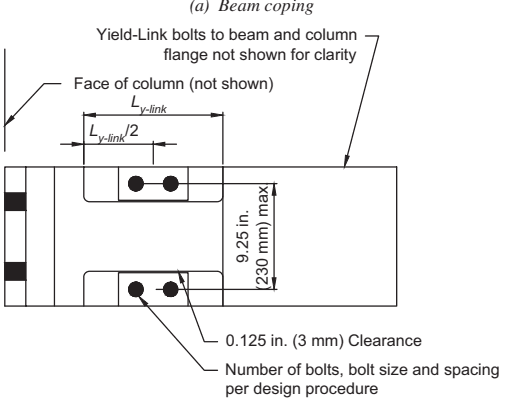
Figure description:
Subject: Beam coping diagram for a Yield-Link structural connection.
Key Entities and Information:
- Yield-Link Connection: Structural detail showing coping on a beam flange.
- Yield-Link Bolts: Indicated positions for bolts to beam and column flange (bolts and column not shown for clarity.
- Dimensions:
- : Specified length for the link area.
- : Midpoint dimension.
- Max Width: maximum vertical span between copes.
- Clearance: gap specified at the cope.
- Design Specifications: The number, size, and spacing of bolts are determined by the specific design procedure.
- (b) Buckling restraint spacer plate placemen
Fig. 12.3(a–b) Connection detailing.
connections and all load combinations specified by the applicable building code. Estimate the design story drift for compliance with the applicable limits specified by the applicable building code as 1.2 times larger than the value calculated assuming fully restrained connections.
Step 2. Check the strength and deflection of the beam assuming the beam is simply supported between shear-plate connections. Check the beam strength for the applicable vertical load combinations of the applicable building code. Check that the deflection of the beam under dead and live loads is less than , where is the length of the beam between the center of the shear-plate shear bolts at each end of the beam.
User Note: The deflection check serves to estimate beam stiffness needed to limit member end rotations. Other values may be acceptable.
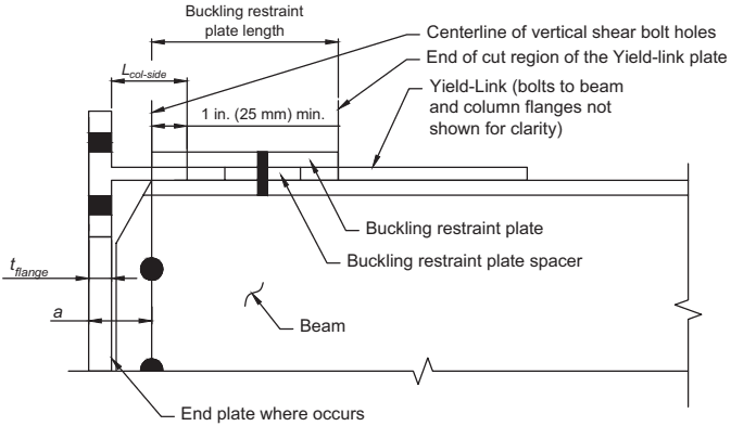
Figure description:
Key Entities and Details:
- Components: Beam, End plate, Yield-Link plate, Buckling restraint plate, and Buckling restraint plate spacer.
- Dimensions:
- : Distance from the end plate to the beginning of the buckling restraint plate.
- Buckling restraint plate length: Total length of the restraint plate.
- : Distance from the inner face of the end plate to the centerline of vertical shear bolt holes.
- : Thickness of the column flange or end plate.
- Key Requirements:
- A minimum distance of 1 in. (25 mm is required between the start of the buckling restraint plate and the end of the cut region of the Yield-link plate.
- The buckling restraint plate terminates at the end of the Yield-link's cut region.
(c) Buckling restraint plate and Yield-Link Lcol-side limitations
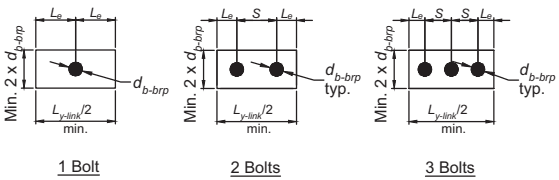
Figure description:
The image illustrates dimensional limitations for buckling restraint plates (BRP and Yield-Link -side connections featuring 1, 2, or 3 bolts.
Key Dimensional Parameters:
- Plate Width (Vertical: Minimum .
- Plate Length (Horizontal: Minimum .
- Edge Distance (: The distance from the center of the outermost bolt(s to the edge of the plate.
- Bolt Spacing (: The center-to-center distance between adjacent bolts (applicable for 2 and 3 bolt configurations.
- Bolt Diameter (: The diameter of the bolts used in the connection.
Configurations:
- 1 Bolt: Single centered bolt with edge distance on both sides.
- 2 Bolts: Two bolts separated by distance , with edge distance at each end.
- 3 Bolts: Three bolts separated by distance , with edge distance at each end.
- (d) Buckling restraint spacer plate dimensions Fig. 12.3(c–d). Connection detailing.
Step 3. Estimate the required Yield-Link yield strength from Step 1 and then calculate the required Yield-Link area.
| P'y-link = Mu/(φbd) | (12.9-1) |
| A'y-link = P'y-link / Fy-link | (12.9-2) |
where
specified minimum yield stress of Yield-Link stem material, ksi (MPa)
Step 4. Determine the nonreduced width and length of the Yield-Link at column side; see Figure 12.2(a).
Step 4.1. Determine nonreduced Yield-Link stem widths, and .
User Note: Try setting and equal to the minimum of beam flange width and column flange width, respectively.
Step 4.2. Nonreduced Yield-Link stem length at column side, , shall have a maximum length equal to 5 in. (125 mm) and a minimum length equal to in. . See Figure 12.3(c).
Step 5. Determine the width of the yielding section of the Yield-Link stem, , where the thickness of the Yield-Link stem, , shall be taken as in. minimum and 1 in. (25 mm) maximum.
(12.9-3)
The value of shall not exceed the least of , or 6 in. (150 mm).
Step 6. Determine the minimum yielding length of the Yield-Link stem, , such that the axial strain in the straight portion of the Yield-Link is less than or equal to 0.085 in./in. at 0.05 rad of connection rotation.
Step 7. Compute the expected yield strength and probable maximum tensile strength of the Yield-Link.
| Pye-link = Ay-linkRyFy-link | (12.9-5) |
| Pr-link = Ay-linkRfFu-link | (12.9-6) |
where
- of reduced Yield-Link section , in.
Step 8. Determine the nonreduced width, , and length, , at beam side of the Yield-Link using from Step 7.
Step 8.1. Design bolts for shear transfer between the Yield-Link stem and the beam flange according to the AISC Specification and determine the bolt diameter, .
Step 8.2. Determine the nonreduced width of the Yield-Link stem on the beam side, .
User Note: Try setting equal to from Step 4.1.
- Step 8.3. Compute the nonreduced length of the Yield-Link stem at beam side, :
(12.9-7)
where
number of rows of bolts from Step 8.1.
- spacing between rows of bolts for Yield-Link stem-to-beam flange connection, minimum
Step 8.4. Check the Yield-Link stem at the beam side for tensile yielding, tensile rupture, block shear rupture, and bolt bearing (where deformation at the hole is a design consideration) according to the AISC Specification. Check the beam flange for bolt bearing (where deformation at the bolt hole is a design consideration) and block shear rupture according to the AISC Specification.
Step 9. Design the Yield-Link flange-to-column flange or end-plate connection using from Step 7.
Step 9.1. Design bolts for tension force transfer between the Yield-Link flange or end plate and the column flange according to the AISC Specification and determine the diameter of the flange bolts, . The required tensile force per bolt in the Yield-Link flange-to-column flange connection, , is:
For T-stub Yield-Link
(12.9-8)
For end-plate Yield-Link
where and are defined in Table 6.2 of Chapter 6, Bolt Unstiffened (BUEEP) and Stiffened Extended End-Plate (BSEEP) Moment Connections.
Step 9.1a. For end-plate Yield-Link connections, check bolt shear rupture strength of the connection provided by bolts at the compression flange only using Equation 6.7-11 in Chapter 6.
Step 9.2. Compute the thickness of the Yield-Link flange, , required to prevent prying action:
(12.9-10)
(12.9-11)
where
- vertical distance from centerline of bolts in Yield-Link flange to face of Yield-Link stem, in. (mm)
- minimum of or , in. (mm)
Step 9.3. Check the thickness of the Yield-Link flange, , for shear yielding and shear rupture according to the AISC Specification.
Step 9.3a. For end-plate Yield-Link connections, check shear yielding and shear rupture of the extended portion of the end plate using Equations 6.7-7 and 6.7-8 in Chapter 6.
Step 9.3b. For end-plate Yield-Link connections, check bolt bearing and tearout failure of the end plate and column flange using Equation 6.7-12 in Chapter 6.
Step 9.4. Design the stem-to-flange weld of the Yield-Link as either a CJP weld or a double-sided fillet weld that will develop the tensile strength of the Yield-Link at the column side, .
(12.9-12)
Step 10. Design the buckling restraint assembly.
Step 10.1. Determine the minimum thickness of the buckling restraint plate (BRP) to prevent yielding during compression of the link stem. BRP thickness shall not be less than 7/8 in. (22 mm).
(12.9-13)
where
Step 10.2. Determine minimum beam flange thickness to prevent yielding and BRP bolt induced prying, . Minimum flange thickness shall not be less than 0.4 in.
(12.9-14)
where
g = gap increase due to transverse shortening of the Yield-Link thickness, in. (mm)
(12.9-19)
(12.9-20)
(12.9-21)
Step 10.3. Determine the BRP bolt size and quantity.
Design BRP bolts for tension + shear interaction for out-of-plane thrust according to the AISC Specification, where is from Step 10.2 and the shear is
(12.9-22)
where is the coefficient of dry kinetic friction, taken as 0.3 .
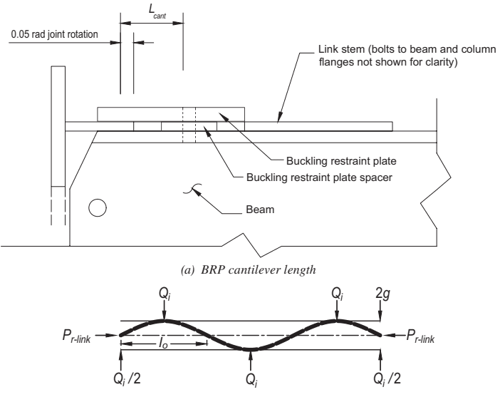
Figure description:
(a BRP cantilever length
- Key Components:
- Beam: Main structural support.
- Link stem: Horizontal component bolted to beam and column flanges.
- Buckling restraint plate (BRP: Top plate secured over the link stem.
- Buckling restraint plate spacer: Positioned between the BRP and the link stem.
- Key Dimensions/Parameters:
- : BRP cantilever length.
- 0.05 rad joint rotation: Indicated displacement at the link end.
(b Buckling wavelength and thrust forces
- Key Entities & Mechanics:
- Sinusoidal Waveform: Represents the buckled shape of the link.
- : Axial thrust forces applied at both ends.
- : Concentrated transverse forces at peak/trough locations.
- : Reaction forces at the end supports.
- : Half-wavelength distance.
- : Total gap width or amplitude of the buckling restraint boundary.
(b) Buckling wavelength and thrust forces
Fig. 12.4. Buckling restraint assembly parameters.
Check the BRP bolts for the in-plane shear thrust force exerted on each spacer plate, , in the strong-axis direction:
(12.9-23)
where
- strong-axis moment of inertia of reduced link stem region, in.
- c = clearance between the Yield-Link and the buckling restraint spacer plate = 1/8 in. (3 mm)
Step 11. Verify the elastic frame drift and connection moment demand by accounting for actual connection stiffness.
Step 11.1. Model the connection using a pair of nonlinear axial links or a nonlinear rotational spring at each connection determined from the following properties:
(12.9-25)
- connection = when more than four bolts are used at Yield-Link-to-beam connection
- (12.9-26)
effective elastic axial stiffness of Yield-Link, kip/in. (N/mm)
(12.9-27)
(12.9-28)
(12.9-29)
(12.9-30)
(12.9-31)
(12.9-32)
= connection rotation at expected yield of Yield-Link, rad
(12.9-33)
All other terms were previously defined or shown in Figure 12.2. Refer to Figure 12.5(a) for a plot of Yield-Link axial force versus Yield-Link axial deformation. Refer to Figure 12.5(b) for the moment versus rotation relationship required for the analysis and modeling of the SST moment connection.
Step 11.2. Considering the applicable drift limit and all applicable load combinations specified by the applicable building code, but not including the overstrength seismic load, verify that:
- (a) The connection moment demand, , is less than or equal to the connection available flexural strength, , taking as 0.90 and as .
- (b) The drift complies with applicable limits.
Adjust connection stiffness and/or number of connections as needed to comply.
Step 12. Determine the required shear strength, , of the beam and beam web-to-column flange connection using
(12.9-34)
where
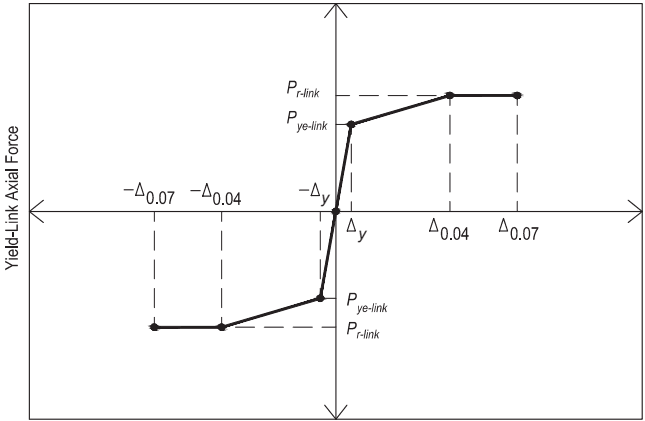
Figure description:
Characteristic Curve of Yield-Link Axial Force
Yield-Link Axial Force vs. Displacement
Annotations
- P_r-link (text_label - position: y-axis (positive and negative))
- P_ye-link (text_label - position: y-axis (positive and negative))
- Δ_y (text_label - position: x-axis)
- -Δ_y (text_label - position: x-axis)
- Δ_0.04 (text_label - position: x-axis)
- -Δ_0.04 (text_label - position: x-axis)
- Δ_0.07 (text_label - position: x-axis)
- -Δ_0.07 (text_label - position: x-axis)
| Displacement (Δ) | Yield-Link Axial Force (P) |
|---|---|
| -Δ_0.07 | -P_r-link |
| -Δ_0.04 | -P_r-link |
| -Δ_y | -P_ye-link |
| 0 | 0 |
| Δ_y | P_ye-link |
| Δ_0.04 | P_r-link |
| Δ_0.07 | P_r-link |
Notes: The figure illustrates a symmetric, piecewise linear relationship between yield-link axial force and displacement. Key stages include an initial linear-elastic portion up to the yield point (Δ_y, P_ye-link, followed by a hardening region reaching (Δ_0.04, P_r-link, and a final plateau between Δ_0.04 and Δ_0.07.))
Yield-Link Axial Deformation
(a) Yield-Link axial force vs. Yield-Link axial deformation
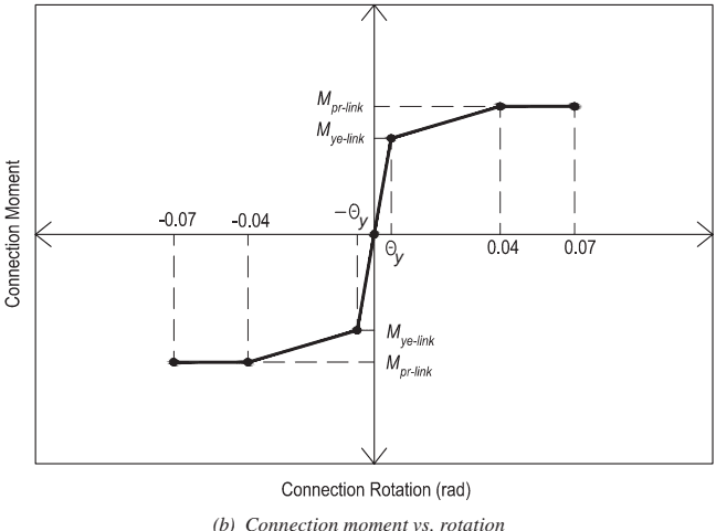
Figure description:
(b Connection moment vs. rotation
Connection moment vs. rotation
Annotations
- (text_label - position: y-axis (positive))
- (text_label - position: y-axis (positive))
- (text_label - position: y-axis (negative))
- (text_label - position: y-axis (negative))
- (text_label - position: x-axis (positive))
- (text_label - position: x-axis (negative))
| Connection Rotation (rad) | Connection Moment |
|---|---|
| -0.07 | - |
| -0.04 | - |
| - | - |
| 0 | 0 |
| 0.04 | |
| 0.07 |
Notes: The chart displays a symmetric, piecewise linear backbone curve representing a connection's moment-rotation behavior. The graph includes key parameters: yield moment () at yield rotation (), and a peak/residual moment () reached at a rotation of 0.04 rad, which then stays constant until 0.07 rad.
Fig. 12.5. Simpson Strong-Tie moment connection modeling parameters.
plate connection shall be determined from a free-body diagram of the portion of the beam between the shear plate connections.
User Note: The load combination of 1.2D + f1L + 0.15S is in conformance with ASCE/SEI 7-22. When using the International Building Code, a factor of 0.7 must be used in lieu of the factor of 0.15 for S (snow) when the roof configuration is such that it does not shed snow off the structure.
Step 13. Verify the beam and column sizes selected in Step 1.
Step 13.1. Beams shall satisfy the AISCSpecification considering the following:
- (a) Vertical load from all applicable load combinations.
- (b) Axial force due to seismic effects determined as the minimum of the maximum the system can deliver or as determined from the overstrength seismic load.
- (c) The application of at each end of the beam as required.
Step 13.2. Column strength shall satisfy the AISC Specification considering loads from all applicable load combinations in the applicable building code, where the seismic effects are determined from the minimum of either the maximum the system can deliver or the overstrength seismic loads. According to Section 12.3.2(7), if column bracing is only provided at the level of the top flange of the beam, in addition to the requirements of the AISC Specification, the maximum available flexural strength of the column outside the panel zone, , shall be taken as , where .
Step 14. Check the column-beam relationship limitations according to Section 12.4.
Step 15. Design the beam web-to-column flange connection for the following required strengths:
moment in shear plate at column face, kip-in. (N-mm)
- required axial strength of the connection, taken as the minimum of the following:
- (1) The maximum axial force the system can deliver.
- (2) The axial force calculated using the load combinations of the applicable building code, including the overstrength seismic load.
- from Step 12.
Step 15.1
- (a) Calculate the maximum shear plate bolt shear, , by sizing the shear plate central bolt to take the required axial and shear load from the beam.
(12.9-35)
where
total number of horizontal bolts resisting axial force in the shear plate in line with the central bolt
total number of vertical bolts resisting shear force in the shear plate
(b) Select a bolt diameter, , that satisfies the AISC Specification.
Step 15.2. Determine the shear-plate geometry required to accommodate a connection rotation of ±0.07 rad.
(12.9-36M)
(12.9-37M)
where
diameter of bolts in shear plate, in. (mm)
horizontal bolt spacing, in. (mm)
vertical bolt spacing, in. (mm)
Step 15.3. Check the shear plate for tension and shear yielding, tension and shear rupture, block shear, combined tension and flexural yielding at the column face, and bolt bearing, where deformation at the bolt hole is a design consideration, according to the AISC Specification.
Step 15.4. Size the weld at the shear plate-to-column flange or end-plate joint to develop the plate in shear, tension, and bending. For double fillet welds, the minimum leg size shall be .
Step 15.5. Check the beam web for tension and shear yielding, tension and shear rupture, block shear, and bolt bearing, where deformation at the bolt hole is a design consideration, according to the AISC Specification.
Step 15.6. Detail the beam flange and web cope such that the flange begins at a point aligned with the centerline of the shear-plate shear bolts. Check entering and tightening clearances as appropriate. See Figure 12.3(a).
User Note: Checking the beam web for flexure at the cope is not required because the flange copes do not extend beyond the centerline of the shear bolts in the beam shear-plate connection.
Step 16. Check the column panel-zone shear strength in accordance with the AISCSpecification. The required shear strength shall be determined from the summation of the probable maximum axial strengths of the Yield-Link. Doubler plates shall be used as required.
Step 17. Check the column web for the concentrated force(s) of according to the AISC Specification.
Step 18. Check the minimum column flange thickness for flexural yielding:
(12.9-38)
where
specified minimum yield stress of column flange material, ksi (MPa)
column flange yield line mechanism parameter from Table 6.5 or 6.3 . For connections away from column ends, Table 6.5 shall be used. For connections at column ends, Table 6.3 shall be used. An unstiffened column flange connection at the end of a column may be used where a rational analysis demonstrates that the unstiffened column flange design flexural strength, as controlled by flexural yielding of the column flange, meets or exceeds the connection moment demand,
Step 19. If a continuity plate or stiffener plate is required for any of the column limit states in Steps 17 and 18, the required strength, , is
(12.9-39)
where
design strengthss from Step 17, kips (N)
Step 19.1. Design the continuity plate or stiffener plate according to the AISC Specification.
Step 19.2. Design the stiffener-to-column web weld and the stiffener to-column flange weld according to the AISC Specification.
The continuity plate or stiffener shall conform to AISC Specification Section J10.8 and shall have a minimum thickness of 1/4 in. (6 mm).