The DuraFuse Frames connection is prequalified for use in special moment frame (SMF) and intermediate moment frame (IMF) systems within the limits of these provisions.
Exception: DuraFuse Frames connections in SMF systems with concrete structural slabs are only prequalified if the concrete structural slab is isolated in accordance with Section 2.3.4.
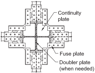
Figure description:
Structural Diagram: Four-sided Flanged Cruciform Connection
Key Components:
- Continuity Plate: Internal horizontal reinforcement within the column assembly.
- Fuse Plate: External bolted plates connecting beam flanges to the column.
- Doubler Plate: Vertical reinforcement on the column web (used when needed.
Contextual Details:
- Application: Part of a DuraFuse Frames connection for Special Moment Frame (SMF systems.
- Requirement: Prequalified for use with concrete structural slabs only if the slab is isolated per Section 2.3.4.
(a) Four-sided flanged cruciform
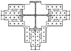
Figure description:
Technical diagram of a three-sided flanged cruciform structural joint.
Key Entities and Details:
- Central Core: A cruciform (cross-shaped intersection of structural steel members.
- Connection Flanges: Three extending flanged plates located on the left, right, and bottom sides.
- Bolt Holes: Multiple circular bolt hole patterns on each flange for mechanical fastening.
- Structural Lines: Solid lines represent visible edges and welds; dashed lines indicate centerlines and hidden internal geometry.
(b) Three-sided flanged cruciform
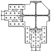
Figure description:
Two-sided flanged cruciform connection (technical drawing
- Central Core: Intersecting I-beam profiles forming a cruciform (cross shape.
- Connection Plates: Large gusset plates extending from the left and bottom arms of the cruciform.
- Fastening Elements:
- Multiple circular bolt hole patterns for structural attachment.
- Horizontal and vertical slotted holes for alignment adjustment.
- Fabrication Details: Weld symbols indicating joints between the central beams and the peripheral flange plates.
(c) Two-sided flanged cruciform
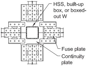
Figure description:
Structural Detail: Four-sided HSS or box connection
- Central Column: HSS (Hollow Structural Section, built-up box, or boxed-out W-shape.
- Connection Components:
- Fuse plates: Four perforated plates extending from each side of the central column.
- Continuity plates: Internal or connecting plates at the column face.
- Configuration: Symmetrical cruciform (four-way arrangement with bolted connections.
(d) Four-sided HSS or box
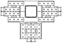
Figure description:
- Type: Technical diagram of a three-sided HSS (Hollow Structural Section or box column connection.
- Central Element: Square-shaped hollow structural section or box column.
- Connection Layout: Three connection assemblies extending from the left, right, and bottom sides of the central column.
- Key Features:
- Each connection plate contains a pattern of circular bolt holes.
- Each plate features two vertically oriented slotted holes.
- Dashed lines indicate internal structural components or hidden edges within the connection.
- Context: Illustrates a specific structural joint configuration for joining three members to a central box column.
(e) Three-sided HSS or box
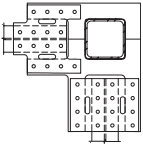
Figure description:
Key Information:
- Type: Technical engineering drawing of a two-sided structural connection.
- Central Member: A square Hollow Structural Section (HSS or box column.
- Connection Configuration: Two orthogonal members connecting to adjacent sides of the central column.
- Connection Plates: Two plates featuring a grid of circular bolt holes and two elongated slotted holes each.
- Details: Dashed lines indicate the profile and centerlines of the connecting members; solid lines outline the connection plates and the central HSS.
(f) Two-sided HSS or box
Fig. 15.2. Bottom views of DuraFuse Frames biaxial configurations.