The design procedure for the SidePlate moment connection system is based on results from both physical testing and detailed nonlinear FEM. The procedure uses an ultimate strength design approach to size the plates and welds in the connection, incorporating strength, plasticity, and fracture limits. For welds, an ultimate strength analysis incorporating the instantaneous center of rotation is used (as described in AISC Steel Construction Manual Part 8). For bolts, an ultimate strength analysis incorporating eccentric bolt group design methodology and instantaneous center of rotation is used (as described in AISC Specification Section J2.4b). Overall, the design process is consistent with the expected seismic behavior of an SMF system: Lateral drifts due to seismic loads induce moments and shear forces in the columns and beams. Where these moments exceed the yield strength of the beam, a plastic hinge will form. While
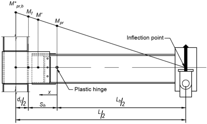
Figure description:
The image is a technical diagram illustrating the moment amplification in a SidePlate moment connection system.
Key Entities and Parameters:
- Moment Values (extrapolated along the beam:
- : Maximum probable moment at the column centerline.
- : Moment at the face of the column.
- : Moment at the edge of the connection plate.
- : Probable plastic moment at the plastic hinge location.
- Structural Components:
- Column: Vertical member on the left.
- Beam: Horizontal member extending to the right.
- Plastic Hinge: Located at distance from the column face.
- Inflection Point: Point of zero moment at the end of the half-span (.
- Geometric Dimensions:
- : Half-depth of the column.
- : Distance from the column face to the center of the plastic hinge.
- : Variable distance from the plastic hinge toward the column.
- : Distance from the plastic hinge to the inflection point.
- : Total distance from the column centerline to the inflection point.
Fig. C-11.3. Amplification of maximum probable plastic hinge moment, , to the column face.
the primary yield mechanism is plastic bending in the beam, in the field-welded connection, a balanced design approach allows for secondary plastic bending to occur within the side plates {A} (hence the reasoning for the protected zones on the side plates {A} for this option). In the field-bolted connection, more conservative side plate {A} design methodology has been developed so that secondary plastic hinging within the side plates {A} does not occur (hence the protected zones on the side plates {A} in this option are not required). Ultimately, the location of the hinge in the beam directly affects the amplification of load (i.e., moment and shear from both seismic and gravity loads) that is resisted by the components of the connection, the column panel zone, and the column, as shown in Figure C-11.3. Each connection component can then be designed to resist its respective load demands induced by the seismic drift (including any increases due to shear amplification as measured from the plastic hinge location in the beam).
For the SidePlate moment connection, all of the connection details—including the sizing of connection plates, angles, fillet welds, and bolts—are designed and provided by engineers at SidePlate Systems. The design of these details is based on basic engineering principles, plastic capacities validated by full-scale testing, and nonlinear FEA. A description of the design methods is presented in Step 7. The initial design procedure for the engineer of record in designing a project with SidePlate moment connections largely involves:
Sizing the frame’s beams and columns, shown in Steps 1 and 2.
Checking applicable building code requirements and performing a preliminary compliance check with all prequalification limitations, shown in Steps 3 and 4.
Verifying that the SidePlate moment connections have been designed with the correct project data as outlined in Step 5 and are compliant with all prequalification limits, including final column-beam relationship limitations as shown in Steps 6, 7, and 8.
Step 1. Equations 11.4-1a/11.4-1aM and 11.4-1b/11.4-1bM should be used as a guide in selecting beam and column section combinations during design iterations.
Satisfying these equations minimizes the possibility of incompatible beam and column combinations that cannot be fabricated and erected or that may not ultimately satisfy column-beam moment ratio requirements.
Step 2. The SidePlate moment connection design forces a plastic hinge to form in the beam beyond the extension of the side plates {A} from the face of the column (side plate {A} extension in Figure 11.9). Because inelastic behavior is forced into the beam at the hinge, the effective span of the beam is reduced, thus increasing the lateral stiffness and strength of the frame (see Figure C-11.4). This increase in stiffness and strength provided by the two parallel side plates {A} must be simulated when creating elastic models of the steel frame. Many commercial structural analysis software programs have a built-in feature for modeling the stiffness and strength of the SidePlate moment connection.
Step 5. Some structural engineers design moment-frame buildings with a lateral-only computer analysis. The results are then superimposed with results from additional lateral and vertical load analysis to check beam and column stresses. Because these additional lateral and vertical loads can affect the design of the SidePlate moment connection, they must also be submitted with the lateral-only model forces. Such additional lateral and vertical loads include drag and chord forces, factored shear loads at the plastic hinge location due to gravity loads on the moment frame beam itself, loads from gravity beams framing into the face of the side plates {A}, and gravity loads from cantilever beams (including vertical loads due to earthquakes) framing into the face of the side plates {A}.
There are instances where an in-plane lateral drag or chord axial force needs to transfer through the SidePlate moment connection, as well as instances where it is necessary to transfer lateral drag or chord axial forces from the orthogonal direction through the SidePlate moment connection. In such instances, these loads must be submitted in order to properly design the SidePlate moment connection for these conditions.
Step 6 of the procedure requires SidePlate Systems to review the information received from the structural engineer, including the assumptions used in the generation of final beam and column sizes to ensure compliance with all applicable building code requirements and prequalification limitations contained herein. Upon reaching concurrence with the structural engineer of record that beam and column sizes are acceptable and final, SidePlate Systems creates a load matrix of the entire structure with these member sizes, including all submitted applicable loads and forces, and designs and details all of the SidePlate moment connections for a specific project in accordance with Step 7. Any changes in member sizes, loads, or forces need to be coordinated with SidePlate Systems because such changes will typically require this step to be repeated.
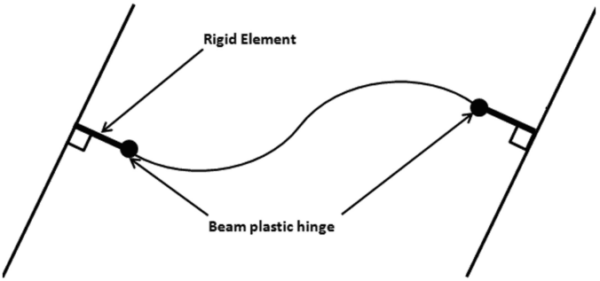
Figure description:
The image is a structural diagram illustrating increased frame stiffness via a reduction in the effective span of a beam. Key entities and details include:
- Parallel Supports: Two slanted parallel lines representing structural columns or supports.
- Rigid Elements: Thick horizontal segments perpendicular to the supports, labeled as "Rigid Element."
- Beam Plastic Hinges: Represented by black circular nodes at the ends of the rigid elements.
- Beam Span: A curved line connecting the two plastic hinges, showing the effective deformable length of the beam.
- Geometric Notation: Right-angle symbols indicate the rigid elements are fixed perpendicular to the vertical supports.
Fig. C-11.4. Increased frame stiffness with reduction in effective span of the beam.
The SidePlate moment connection design procedure is based on the idealized primary behavior of an SMF system—the formation of a plastic hinge in the beam outside of the connection. In the field-welded connection, although the primary yield mechanism is the development of a plastic hinge in the beam near the end of the side plate {A}, secondary plastic behavior (plastic moment capacity) is developed within the side plates {A} themselves, at the face of the column (this is not the case for the field-bolted connections). Overall, a balanced design is used for the connection components to ensure that the plastic hinge will form at the predetermined location. The demands on the connection components are a function of the strain-hardened flexural strength of the beam, the gravity loads carried by the beam, and the relative locations of each component and the beam plastic hinge. Connection components closer to the column centerline are subjected to increased moment amplification compared to components located closer to the beam plastic hinge as illustrated in Figure C-11.3.
Step 7 of the process requires that SidePlate Systems design and detail the connection components for the actions and loads determined in Step 6. The procedure uses an ultimate strength design approach to size plates, bolts, and welds, thus incorporating strength, plasticity, and fracture limits. For welds, an ultimate strength analysis incorporating the instantaneous center of rotation is used (as described in AISC Steel Construction Manual Part 8). For bolts, an ultimate strength analysis incorporating eccentric bolt group design methodology and instantaneous center of rotation is used (as described in AISC Specification Section J2.4b). Overall, the design process is consistent with the expected seismic behavior of an SMF system as described previously.
The SidePlate moment connection components are divided into four distinct design groups:
- (1) Load transfer out of the beam
- (2) Load transfer into the side plates {A}
- (3) Design of the side plates { A } at the column face
- (4) Load transfer into the column
The transfer of load out of the beam is achieved through welds {4} and {5}. The loads are in turn transferred through the vertical shear elements {E} and cover plates {B} into the side plates {A} by either welds {6} and {7} (field-welded) or bolt group (field-bolted). The load at the column face (gap region) is resisted solely by the side plates {A}, which transfers the load directly into the column through weld {2} and weld {1} in a box or HSS. In a wide-flange column, the load is transferred through weld {2} and indirectly through weld {3} through the combination of weld {1} and the horizontal shear plates {D}. At each of the four design locations, the elements are designed for the combination of moment, , and shear, .
Connection Design
Side Plate {A}, Field-Welded. To achieve the balanced design for the connection—the primary yield mechanism developing in the beam outside of the connection with secondary plastic behavior within the side plates {A}—the required minimum thickness of the side plate {A} is calculated using an effective side plate {A} plastic section modulus, , generated from actual side plate {A} behavior obtained from stress and strain profiles along the depth of the side plate {A}, as recorded in test data and nonlinear analysis (see Figure C-11.5). The flexural strength of the plates, , is then calculated using the simplified and an effective plastic stress, , of the plate. Allowing for yielding of the plate as observed in testing and analyses (see Figure C-11.6) and comparing to the design demand, , calculated at the face of column gives:
(C-11.7-1)
where
Side Plate {A}, Field-Bolted. The required minimum thickness of the side plate {A} is calculated based on the engineering principals of the fully yielded section at either the column face or at the location of the first bolt as shown in Figures C-11.7(a) and C-11.7(b). The section of the side plate {A} at the column face has larger design demand in comparison with that of the net section at the location of the first bolt so the required minimum thickness will be the greater of the two design checks.
To ensure the proper behavior of the side plate {A} and to preclude undesirable limit states, such as buckling or rupture of the side plate {A}, the ratio of the gap distance between the end of the beam and the face of the column to the side plate
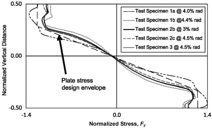
Figure description:
Normalized Stress vs. Normalized Vertical Distance
Legend
- Test Specimen 1a @ 4.0% rad — color: black; symbol: Dash-dot line
- Test Specimen 1b @ 4.4% rad — color: gray; symbol: Dashed line
- Test Specimen 2b @ 3% rad — color: black; symbol: Thick solid line
- Test Specimen 2c @ 4.5% rad — color: black; symbol: Dashed line
- Test Specimen 3 @ 4.5% rad — color: black; symbol: Thin solid line
Annotations
- Plate stress design envelope (text_label - position: arrow pointing to (x ≈ -0.7, y ≈ 0.2))
| Normalized Vertical Distance | Test Specimen 1a @ 4.0% rad | Test Specimen 1b @ 4.4% rad | Test Specimen 2b @ 3% rad | Test Specimen 2c @ 4.5% rad | Test Specimen 3 @ 4.5% rad |
|---|---|---|---|---|---|
| 0.50 | -1.10 | -1.00 | -1.02 | -1.02 | -1.02 |
| 0.45 | -1.25 | -1.05 | -1.05 | -1.05 | -1.05 |
| 0.40 | -1.40 | -0.95 | -1.08 | -1.08 | -1.08 |
| 0.35 | -1.35 | -0.90 | -1.05 | -1.05 | -1.05 |
| 0.30 | -1.25 | -0.85 | -1.00 | -1.02 | -1.00 |
| 0.25 | -1.15 | -0.60 | -0.95 | -0.98 | -0.95 |
| 0.20 | -1.00 | -0.40 | -0.75 | -0.80 | -0.75 |
| 0.15 | -0.60 | -0.30 | -0.50 | -0.55 | -0.50 |
| 0.10 | -0.40 | -0.20 | -0.30 | -0.35 | -0.30 |
| 0.05 | -0.20 | -0.10 | -0.15 | -0.18 | -0.15 |
| 0.00 | 0.00 | 0.00 | 0.00 | 0.00 | 0.00 |
| -0.05 | 0.20 | 0.10 | 0.15 | 0.18 | 0.15 |
| -0.10 | 0.40 | 0.20 | 0.30 | 0.35 | 0.30 |
| -0.15 | 0.60 | 0.30 | 0.50 | 0.55 | 0.50 |
| -0.20 | 1.00 | 0.40 | 0.75 | 0.80 | 0.75 |
| -0.25 | 1.15 | 0.60 | 0.95 | 0.98 | 0.95 |
| -0.30 | 1.25 | 0.85 | 1.00 | 1.02 | 1.00 |
| -0.35 | 1.35 | 0.90 | 1.05 | 1.05 | 1.05 |
| -0.40 | 1.40 | 0.95 | 1.08 | 1.08 | 1.08 |
| -0.45 | 1.25 | 1.05 | 1.05 | 1.05 | 1.05 |
| -0.50 | 1.10 | 1.00 | 1.02 | 1.02 | 1.02 |
Notes: The x-axis represents Normalized Stress (Fy and the y-axis represents Normalized Vertical Distance. The chart shows the stress distribution across the normalized vertical distance for various test specimens at specific radial percentages.)
Fig. C-11.5. Stress profile along depth of side plate {A} at the column face at maximum load cycle.
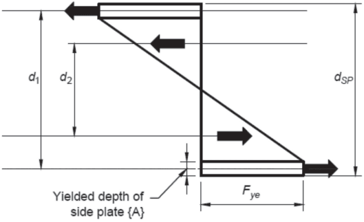
Figure description:
Idealized Plastic Stress Distribution (Fig. C-11.6
- Purpose: Used to compute the effective plastic modulus ( of a side plate.
- Key Dimensions:
- : Total depth of the side plate.
- : Vertical distance between the outer stress blocks.
- : Vertical distance between inner stress components.
- Key Entities:
- Yielded depth of side plate {A}: Height of the outer rectangular sections showing full yielding.
- : Yield stress magnitude represented by the width of the distribution.
- Force Arrows: Indicate opposing tension and compression forces across the horizontal neutral axis.
- Distribution Shape: A combined rectangular (at outer edges and triangular (approaching neutral axis stress profile.
Fig. C-11.6. Idealized plastic stress distribution for computation of the effective plastic modulus, , of the side plate.
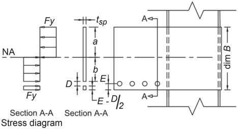
Figure description:
Subject: Idealized plastic stress distribution for calculating the effective plastic modulus ( of a side plate.
Key Entities and Dimensions:
- Side Plate: Rectangular plate with height dim B and thickness .
- Neutral Axis (NA: Dividing line for the stress distribution.
- Geometric Parameters:
- : Distance from to the top of the plate.
- : Distance from to the top of the first hole.
- : Diameter/dimension of the hole.
- : Edge distance or spacing related to hole placement.
- Stress Diagram (Section A-A:
- Shows a constant yield stress above and below the neutral axis.
- Stress distribution is interrupted (zero at the location of the holes.
- Stress direction reverses at the neutral axis to represent plastic bending.
(a) Side plate {A} elevation view and stress diagram at the net section
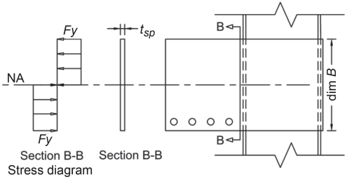
Figure description:
- Diagram Type: Side plate elevation view and corresponding stress diagram at Section B-B.
- Key Entities:
- Side Plate: Height labeled as "dim ".
- Section B-B: Cross-section showing plate thickness (.
- Neutral Axis (NA: Horizontal dashed line dividing the stress zones.
- Stress Diagram: Shows a fully plastic distribution at yield stress , with compression (left arrows above the NA and tension (right arrows below it.
- Structural Features: The side plate is connected to a vertical column; four circular holes are visible at the bottom left of the plate.
(b) Side plate {A} elevation view and stress diagram at the column face
Fig. C-11.7. Side plate {A} elevation view and stress diagrams for configuration A (standard).
{A} thickness is kept within a range for all connection designs. The optimum gap-to-thickness ratio has been derived based upon the results of full-scale testing and parametric nonlinear analysis.
Cover Plate {B}. The thickness of the cover plates {B} is determined by calculating the resultant shear force demand, , from the beam moment couple as:
(C-11.7-2)
and by calculating the vertical shear loads, resisted through the critical shear plane of the cover plates {B}.
The critical shear plane for the field-welded connection is defined as a section cut through the cover plate {B} adjacent to the boundary of weld {7}, as shown in Figure C-11.8(a). Hence, the thickness, , of the cover plate {B} is:
(C-11.7-3)
where
The top cover plate {B} in the field-bolted connection (standard configuration) is designed based on the block shear check in the critical shear plane which is defined as a section cut through the cover plate {B} through the bolt holes, as shown in Figure C-11.8(b).
Vertical Shear Element (VSE). The thickness of the VSE, if applicable (which may include angles {E} and/or bent plates {C}, as shown in Figures 11.14-11.19), is determined as the thickness required to transfer the vertical shear demand from the beam web into the side plates {A}. The vertical shear force demand, , at this load transfer comes from the combination of the capacities of the cover plates {B} and the VSE. The minimum thickness of the VSE, , to resist the vertical shear force is computed as follows:
(C-11.7-4)
where
calculated vertical shear demand resisted by VSE, kips (N)
depth of vertical shear element, in. (mm)
Horizontal Shear Plate (HSP) {D}. The thickness of the HSP {D}, if applicable (see Figures 11.14–11.19), is determined as the thickness required to transfer the horizontal shear demand from the top (or bottom) of the side plates {A} into the column web. The shear demand on the HSP is calculated as the design load developed through the fillet weld connecting the top (or bottom) edge of the side plates {A} to the HSP (weld {1}). The demand force is determined using an ultimate strength analysis of the weld group at the column (weld { 1 } and weld { 2 }) as described in the following section.
(C-11.7-5)
where
effective length of horizontal shear plate {D}, in. (mm)
Welds. Welds are categorized into three weld groups and sized using an ultimate strength analysis.
The weld groups are categorized as follows (see Figures 11.14-11.21 and Figure C-11.9):
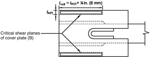
Figure description:
Field-welded connection diagram
- Subject: Critical shear planes of cover plate {B}.
- Key Entities: Cover plate, longitudinal welds, and designated critical shear planes.
- Dimensional Formulas:
- : Weld thickness/throat dimension.
- Detail: Illustrates the length and location of critical shear planes relative to the weld group.
(a) Field-welded connection
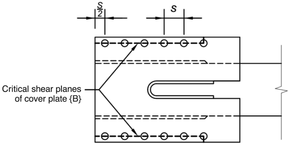
Figure description:
Type: Technical diagram of a field-bolted connection for a cover plate.
Key Entities & Information:
- Cover plate {B}: The primary structural component shown in a plan view.
- Critical shear planes: Indicated by arrows pointing to the two longitudinal rows of bolt holes.
- Bolt Holes: Arranged in two parallel horizontal rows.
- Dimensions:
- : Longitudinal center-to-center spacing between bolts.
- : Distance from the plate's leading edge to the center of the first bolt.
- Structural Features: Includes a central U-shaped cutout and internal members indicated by dashed lines.
(b) Field-bolted connection
Fig. C-11.8. Critical shear plane of cover plate {B}.
Weld Group 1—Fillet welds from the beam flange to the cover plate {B}/angles {H} (weld {5} and weld {5a}) and the fillet weld from the beam web to the VSE (weld {4}).
Weld Group 2—Fillet welds from the cover plate {B} to the side plate {A} (weld {7}) and fillet welds from the VSE to the side plate {A} (weld {6}) (only for field-welded connections).
Weld Group 3—Fillet welds from the side plate {A} to the HSP {D} (weld {1}), fillet welds from the side plate {A} to the column flange tips (weld {2}), and fillet welds from the HSP {D} to the column web (weld {3}).
The ultimate strength design approach for the welds incorporates an instantaneous center of rotation method as shown in Figure C-11.10 and described in AISC Steel Construction Manual Part 8.
At each calculation iteration, the nominal shear strength, , of each weld group for a determined eccentricity, , is compared to the demand from the amplified moment to the instantaneous center of the group, . The process is continued until equilibrium is achieved. Because the process is iterative, SidePlate Systems engineers use design calculation software to compute the weld sizes required to achieve the flexural and shear strength needed for each weld group to resist the amplified flexural and vertical shear demand, and , respectively.
Bolts (Field-Bolted Connection Only). The ultimate strength analysis incorporating eccentric bolt group design methodology and instantaneous center of rotation as shown in Figure C-11.11 and described in AISC Specification Section J2.4(b) is
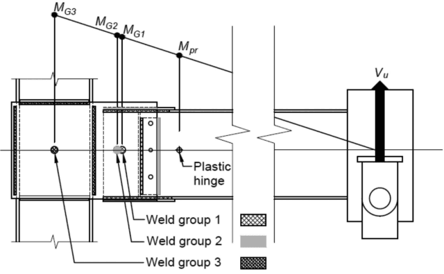
Figure description:
Subject: Structural steel beam-to-column connection diagram (Fig. C-11.9 illustrating weld group locations and associated moment demands.
Key Entities and Information:
- Weld Groups: Three distinct design weld groups are identified by shading patterns:
- Weld group 1: Center-most group in the connection assembly.
- Weld group 2: Intermediate group.
- Weld group 3: Group closest to the column face/centerline.
- Moment Demand (: A linear moment gradient diagram shows specific demand values ( corresponding to the centroids of their respective weld groups.
- Plastic Hinge: A specific location identified on the beam where the probable maximum moment ( is measured.
- Loading: An ultimate shear force ( is applied at the beam's end, driving the moment demand across the connection.
- Assembly: Features a column-beam interface with a field-bolted/welded bracket or splice plate assembly.
Fig. C-11.9. Location of design weld groups and associated moment demand, .
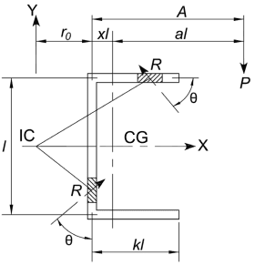
Figure description:
This technical diagram illustrates the instantaneous center of rotation (IC for a C-shaped weld group.
Key Entities and Details:
- Weld Group: A C-shaped configuration with a vertical height and horizontal segments of length .
- CG (Center of Gravity: Located at a horizontal distance from the vertical weld segment.
- IC (Instantaneous Center of Rotation: Located to the left of the weld group at a distance from the vertical weld segment.
- Applied Load (: A downward vertical force applied at a distance from the vertical weld, which is also a distance from the CG (where .
- Resistance (: Reaction force vectors acting on the weld segments at an angle . These vectors are perpendicular to the radius line originating from the IC.
- Coordinate System: X and Y axes are used to define the geometry and force locations.
Fig. C-11.10. Instantaneous center of rotation of a sample weld group.
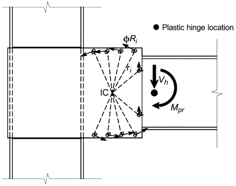
Figure description:
This technical diagram illustrates the Instantaneous Center of Rotation (IC method for a structural bolt or weld group connection between a beam and a column.
Key Entities and Symbols:
- IC (Instantaneous Center of Rotation: The theoretical point about which the connection plate rotates.
- Plastic hinge location: Marked on the beam as the point where seismic forces are applied.
- : Vertical shear force acting at the plastic hinge.
- : Probable maximum moment acting at the plastic hinge.
- : The radial distance from the IC to a specific fastener or weld point.
- : The resisting force vector at a specific point, acting perpendicular to the radius .
- Structural Components: Includes a vertical column, a horizontal beam, and a connecting plate with a group of fasteners (bolts or weld segments.
Fig. C-11.11. Instantaneous center of rotation of a sample bolt group.
used to design the number of required bolts. An iterative process is required to find the solution. At each calculation iteration, the nominal shear strength, , of the bolt group (comprising horizontal and vertical rows of bolts), for a determined eccentricity, , is compared to the demand from the amplified moment and shear to the instantaneous center of the group, . The process is continued until equilibrium is achieved.
Step 8 requires that the engineer of record review calculations and drawings supplied by SidePlate Systems engineers to ensure that all project-specific moment connection designs have been appropriately completed and that all applicable project-specific design loads, building code requirements, building geometry, and beam-to-column combinations have been satisfactorily addressed.
The CPRP has prequalified the SidePlate moment connection after reviewing the proprietary connection design procedure contained in the SidePlate moment connection design software (version 16 for welded and version 17 for bolted), as summarized here. In the event that SidePlate moment connection designs use a later software version to accommodate minor format changes in the software’s user input summary and output summary, the SidePlate moment connection designs will be accompanied by a SidePlate moment connection validation report that demonstrates that the design dimensions, lengths, and sizes of all plates and welds generated using the CPRP-reviewed connection design procedure remain unchanged from that obtained using the later version connection design software. Representative beam sizes to be included in the validation report are W36×150 (W920×223) and W40×294 (W1000×438) for the field-welded and W36×150 (W920×223), W40×211 (W1000×314), and W40×397 (W1000×591) for the field-bolted connection.