The Simpson Strong-Tie® Strong Frame® moment connection uses patented Yield-Link® structural fuse technology to create a field-bolted, partially restrained (PR) moment connection for strong-axis wide-flange beam-to-column connections. The Yield-Links are either configured as separate T-stub elements connected to each beam flange, or they are connected to a common end plate for shallow beam connections. During seismic events, inelastic demand is absorbed in the Yield-Link elements of the beam-to-column connection instead of requiring the formation of a plastic hinge in the beam adjacent to the column. The connection eliminates field welding, and the frame behavior afforded by the connection enables frames to be designed without the need for flange bracing on the beams. This is particularly useful in structures where providing flange bracing can be difficult (such as when integrated into wood structures) or is an undesirable architectural intrusion. Connection testing qualified the use of snug-tight bolts for typical field-installed bolts, simplifying bolt installation, inspection, and frame erection.
The connection centers around the Yield-Link (Link) structural fuse performance and a capacity-based design procedure that, under lateral loading, pushes inelastic demand into the Links rather than the members. Unlike other prequalified special moment frame (SMF) connections, little if any inelastic behavior is expected in the members. Whether configured as a modified T-stub or connected to a common end plate, the Link serves to transfer moment from the beam to the column. The connection bolts to the column flange with four snug-tight ASTM F3125/F3125M Grade A325 or A325M bolts at each link (pretensioned ASTM F3125/F3125M Grade A325, A325M, or F1852 bolt assemblies are also permitted). The stem of the Link bolts to the beam flange with pretensioned ASTM F3125/F3125M Grade A325, A325M, A490, A490M, F1852, or F2280 bolt assemblies. In between the connection to the beam and column, the stem of the Link is elongated and contains a section with reduced area that defines the location of yielding in the Link. This reduced area controls the axial strength of the Link and provides for very reliable estimates of the yield and ultimate moment strength of the beam-to-column connection. To prevent buckling of the yielding section of the Link when in compression, a buckling restraint plate (BRP) is placed over the Link and bolted to the beam flange on either side of the reduced-area section of the Link. The BRP uses snug tight ASTM F3125/F3125M Grade A325 or A325M bolts that pass through a spacer plate that fills the gap between the bottom of the BRP and the near surface of the beam flange. The web of the beam connects to either the column or the common end plate via a single-plate shear connection. The connection uses an arrangement of bolts that permit transfer of shear and axial forces between the beam and column, while at the same time limiting the transfer of moment. This is accomplished by having a central pivot point defined by a central bolt passing through standard holes in both the beam web and the shear plate and by having the remaining bolts in the shear plate pass through either horizontal or vertical slots in the shear plate and standard holes in the beam web. This arrangement creates a hinge in the beam web-to-column flange connection and defines the effective rotation point for the plastic hinge. Shear-plate bolts are permitted to be snug-tight ASTM F3125/F3125M Grade A325 or A325M or pretensioned ASTM F3125/F3125M Grade A325, A325M, or F1852. The hinge is used to transfer net axial force from the beam to the column, so in addition to shear- and moment-related design provisions found in other prequalified moment connections, this connection also contains design provisions for axial load transfer.
Initial qualification testing consisted of a series of nine reversed cyclic tests according to the 2010 AISC Seismic Provisions Section E3.6c (AISC, 2010a) covering three configurations, each with three replications. Each test consisted of a single-story, single-bay frame with lateral loads (in-plane shear) introduced into the top flange of the beam through a wood nailer connected to the beam flange. Only one end of the beam used the Strong Frame connection, and the remaining beam-to-column and column-to-test bed connections were pinned. This configuration was chosen for testing the connection over the typical cantilever beam configuration for two primary reasons: It allowed beam axial loads to be driven through the joint to enable verification of both the axial and moment related design provisions, and it permitted observation of the beam flange response when flange bracing was omitted. The testing resulted in all frames reaching a drift level of 0.05 rad without a loss of strength greater than of the nominal plastic moment strength, , satisfying the requirements of the 2010 AISC Seismic Provisions Section E3.6b. For this connection, is calculated using the yielding area of the links and the connection geometry rather than the beam properties.
At the current time there are no other PR connections that have been prequalified as an SMF connection, and PR SMF connections were not directly addressed in the 2010 AISC Seismic Provisions. The 2016 AISC Seismic Provisions (AISC, 2016a) address the potential use of PR SMF connections in Section E3.6b.(b). Accordingly, even though the initial testing met the SMF connection performance requirements of the 2010 AISC Seismic Provisions, additional requirements were created to demonstrate the suitability of the connection and the design procedure for use as SMF or IMF connections in high-seismic applications.
The first additional requirement was to assess the connection performance through a component equivalency evaluation using the procedures found in FEMA P-795, Quantification of Building Seismic Performance Factors: Component Equivalency Methodology (FEMA, 2011). An independent study was commissioned to perform the FEMA P-795 evaluation, comparing the Strong Frame connection to the reduced beam section (RBS) connection, resulting in two changes to the design procedure. The Link flange-to-stem weld was required to develop the full strength of the unreduced portion of the stem at the column side (it had been previously designed for the probable maximum tensile strength of the reduced yielding area); and a single thickness of stem material, ½ in. (13 mm), was selected (initially different thicknesses were considered). Six additional tests similar to those described previously (three reversed cyclic tests according to the 2010 AISC Seismic Provisions and three monotonic tests) were then conducted to verify the performance with the amended design and detailing procedure.
Although not required by the 2010 AISC Seismic Provisions, the monotonic tests were conducted to satisfy FEMA P-795 requirements. The purpose of the monotonic testing is to better understand the collapse behavior of buildings using the connection by investigating the interstory drift capacity afforded by the connection. The results of the cyclic tests again showed that the connection meets the performance require ments of the 2010 AISC Seismic Provisions and that the ultimate limit state was as predicted: a net section fracture in the reduced portion of the Links. The results of the monotonic tests showed that the connection has tremendous displacement capacity, the tests being stopped at 9.5% interstory drift without failure or decreasing from peak capacity. The conclusion from the FEMA P-795 study was that the Strong Frame connection is equivalent to the prequalified RBS connection. It should be noted that for all the tests—initial and secondary, cyclic and monotonic—yielding initiated from about 0.01 to 0.015 rad interstory drift angle as is typically expected of frames with SMF connections.
Even with the successful FEMA P-795 evaluation, a second additional requirement was added to look more at system behavior rather than the individual connection behavior as was the focus of the FEMA P-795 evaluation. To address this additional requirement, a series of nonlinear response history analyses were performed using a suite of ground motions and a suite of archetype buildings to compare the seismic response of buildings using the Strong Frame connection to buildings using a prequalified connection. The connection chosen for comparison was again the RBS connection. As before, an independent study was commissioned, with designs for both systems minimized to the extent allowed by the respective design procedures. The study included the development of archetype designs for representative steel moment frames for a two-story, four-story, and six-story building using ASCE/SEI 7-10 (ASCE, 2010), the 2010 AISC Specification (AISC, 2010b), and the 2010 AISC Seismic Provisions and was evaluated using seven scaled ground motion pairs. The study demonstrated that the performances of the Strong Frame and comparable RBS structures were very similar and within acceptable levels. No collapses were predicted by the analysis. The most severe response was recorded for the two-story RBS archetype, which exhibited a maximum story drift ratio for one record of nearly 5%. Mean story drift response for both the Strong Frame and RBS structures averaged approximately 2.3%, and the mean plus one standard deviation response averaged 3% for the Strong Frame structures and 2.8% for the RBS structures.
In addition to the cyclic and monotonic testing specifically used to qualify the Strong Frame connection, other large-scale shake table test programs have employed the connection. Steel frames using the Strong-Frame connection were part of the 2009
NEESWood Capstone tests at Japan’s E-Defense facility in Miki, Japan (van de Lindt et al., 2009). The full-scale seven-story structure consisted of first-story steel framing using the Strong Frame connection, which supported a six-story, wood, light-frame structure on top and had a plan dimension of 40 ft by 60 ft (12 m by 18 m). More recently, steel frames using the Strong Frame connection were employed as retrofit elements in the first story of a four-story, full-scale, light-frame, wood building built to simulate a typical San Francisco-style wood structure with a soft/weak first story due to ground-level parking. Known as the NEESSoft project (Bahmani et al., 2016; Pryor et al., 2014; van de Lindt et al., 2016), the building was successfully tested at the NHERI at San Diego (formerly NEES at UCSD) outdoor shake table under a variety of different ground motions.
In 2015, six additional cyclic tests (three each of two configurations) were conducted on small frames employing shallow beams and the end-plate Yield-Link connection, where the single-plate shear connection and the yielding stem of the Yield-Link are all welded to a common end plate, which is then bolted to the column flange. As before, single-story, single-bay frames were tested. Column bases were hinged, and both beam-to-column connections were moment resisting. The smaller of the two frame specimens consisted of 6-in.- (150-mm-) deep welded H-section columns and an 8.5-in.- (220-mm-) deep welded H-section beam in a frame approximately 8 ft (2.4 m) tall by 9.5 ft (2.9 m) wide (to member centerlines). The larger of the frame specimens similarly consisted of 18-in.- (460-mm-) deep welded columns and an 8.5-in.- (220-mm-) deep welded beam in a frame approximately 8 ft (2.4 m) tall by 12 ft (3.7 m) wide. As before, in-plane lateral load was delivered through a wood nailer connected to the top flange of the beam, and the bottom flange remained unbraced. Bolts connecting the yielding stem of the Link to the beam were pretensioned, whereas the remaining bolts at the beam web-to-shear plate, the end plate-to-column flange, and the BRP bolts were all installed snug-tight. There were no observed failures in the smaller frame, and testing was stopped after two cycles of 0.08 rad interstory drift angle. For the larger frame, failure occurred in the Links, with fracture of the yielding area of the Link occurring in the first cycle of 0.08 rad interstory drift angle for one test and in the second cycle of 0.08 rad for the other two tests. All tests met the connection performance requirements in AISC Seismic Provisions Section E3.6b. For the smaller frames, yielding initiated at approximately 0.0125 rad interstory drift angle, whereas it was approximately 0.01 rad for the larger frame.
In 2017, three additional cyclic tests and one monotonic test were conducted to support an expansion of both Yield-Link and member sizes. As before, single-story, single-bay frames were tested with one beam-to-column connection designed as moment resisting using T-stub Yield-Links, with the other beam-to-column connection and both column base connections designed as pins. In-plane lateral load was again delivered to the frame using a wood nailer connected to the top flange of the beam, and also as before, the bottom flange was unbraced. Columns were braced out of plane at the cap plate (slightly above the level of the top flange of the beam) and the column base. Column sections were W36x210 (W920x313), and the beam was W36x170 (W920x253). The center-to-center distance between the two columns was 35 ft (11 m), and the beam centerline was 21.5 ft (6.6 m) above the column base hinges. T-stub Yield-Links were designed for the new maximum size consisting of 1-in.- (25-mm-) thick stem material, with a 6-in.- (150-mm-) wide yield width in the reduced section, which for comparison corresponds to the remaining flange area of a 50% RBS cut on a W36x160 (W920x238). As expected, fracture of the yielding section of the Link was the failure mode in all three cyclic tests. Two of the test specimens completed one cycle of 0.05 rad interstory drift prior to failure, and one completed two cycles of 0.05 rad interstory drift before failure. No failures occurred in the monotonic test, and it was stopped at approximately 0.09 rad interstory drift due to actuator limitations. For both cyclic and monotonic tests, initiation of yielding occurred at approximately 0.01 rad interstory drift angle. The overall tested assembly is shown in Figure C-12.1, and a plot of moment at the face of the column versus story drift is shown in Figure C-12.2.
In accordance with the design procedure, the length of the yielding section of the Links must increase with increasing beam depth. This leads to the need for more than one bolt on each side of the yielding area of the Link securing the BRP to the beam flange, and thicker Links mean more stress on the BRP, their bolts, and the beam flange. Whereas previously the BRP components were based on the empirical results of early testing, the buckling restraint assembly for the W36 (W920) tests previously discussed was designed according to a new set of requirements that add specific design provisions to the empirical minimum requirements.
The inclusion of beams and columns of up to W36 (W920) profiles and Yield-Links of up to 6 in.² yielding area opened up the connection to use in design space that had
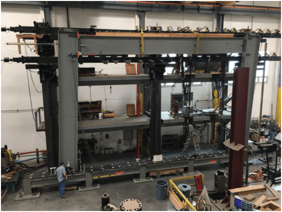
Figure description:
- Subject: Structural laboratory testing of a large-scale steel frame assembly.
- Key Entities:
- Large-scale steel beams and columns: W36 (W920 profiles.
- Yield-Links: Testing a new 6 in.² yielding area size.
- Testing Rig: Industrial-scale hydraulic loading system and structural support frame.
- Personnel: One technician visible at the base for scale.
- Context: Experimental validation of seismic or structural connections in a high-capacity test facility.
Fig. C-12.1. Testing new largest Link size with 6 in.² yield area.
not been studied, specifically taller buildings. In accordance with the 2010 AISC Seismic Provisions, Section E3.6b(b), additional analysis work complying with ASCE/SEI 7-16, Section 12.2.1.1 (ASCE, 2016), was requested by the CPRP committee. To meet this request, a FEMA P-695 (FEMA, 2009) study was conducted to compare the performance of a steel SMF using both RBS connections and Strong-Frame connections. The basis of this comparison came from a previous FEMA P-695 study on 4-, 8-, 12-, and 20-story steel SMF using RBS connections and documented in a report by NIST (NIST, 2010). The NIST RBS frames were reanalyzed to verify the new model was achieving similar results, and then the frames were redesigned for use with the Strong-Frame connection and evaluated using FEMA P-695 procedures. The results showed that for all building heights the buildings with the Strong-Frame connection had better resistance to collapse, and the calculated overstrength ranged from 3.00 to 3.63 for the Strong Frame buildings. Table C-12.1 shows the comparison between the computed collapse margin ratios (CMR) and adjusted collapse margin ratios (ACMR) for both systems. Additional information on the large Link testing, buckling restraint design procedure verification, and FEMA P-695 analysis results is given in Pryor et al. (2018).