9.3.1 Beam Limitations
Beams shall satisfy the following limitations:
- (1) Beams shall be rolled wide-flange or built-up I-shaped members conforming to the requirements of Section 2.3.
- (2) Beam depth is limited to a maximum of W33 (W840) for rolled shapes. Depth of built-up sections shall not exceed the depth permitted for rolled wide-flange shapes.
- (3) Beam weight is limited to a maximum of 130 lb/ft (190 kg/m).
- (4) Beam flange thickness is limited to a maximum of 1 in. (25 mm).
- (5) Beam flange width shall be at least 6 in. (150 mm) for W-series brackets and at least 10 in. (250 mm) for B-series brackets.
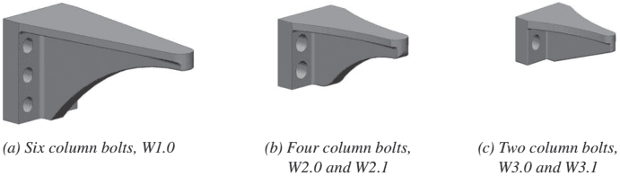
Figure description:
Entity: Cast bolted bracket W-series configurations
- (a W1.0: Configuration with six column bolts.
- (b W2.0 and W2.1: Configuration with four column bolts.
- (c W3.0 and W3.1: Configuration with two column bolts.
Fig. 9.2. Cast bolted bracket W-series configurations.
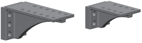
Figure description:
Key Entities and Information:
- Cast Bolted Bracket (W-series: Two configurations of a structural L-shaped cast bracket with a curved support gusset.
- Left Bracket (B1.0 Configuration:
- Column Mounting: 6 vertical bolt holes (3 per side.
- Top Plate: 12 horizontal bolt holes (2 rows of 6.
- Right Bracket:
- Column Mounting: 4 vertical bolt holes (2 per side.
- Top Plate: 8 horizontal bolt holes (2 rows of 4.
(a) Six column bolts, B1.0
(b) Four column bolts, B2.1
Fig. 9.3. Cast bolted bracket B-series configurations.
- (6) The clear span-to-depth ratio of the beam shall be limited to 9 or greater for both SMF and IMF systems.
- (7) Width-to-thickness ratios for the flanges and web of the beam shall conform to the requirements of the AISC Seismic Provisions.
- (8) Lateral bracing of beams shall be provided as follows:
- (a) For SMF systems, in conformance with the AISC Seismic Provisions. Sup- plemental lateral bracing shall be provided at the expected plastic hinge in conformance with the AISC Seismic Provisions.
When supplemental lateral bracing is provided, attachment of supplemental lateral bracing to the beam shall be located at a distance to from the end of the bracket farthest from the face of the column, where is the depth of the beam. No attachment of lateral bracing shall be made to the beam in the region extending from the face of the column to a distance beyond the end of the bracket.
(b) For IMF systems, in conformance with the AIS C Seismic Provisions.
Exception: For both systems, where the beam supports a concrete structural slab that is connected between the protected zones with welded shear connectors spaced at maximum of 12 in. (300 mm) on center, supplemental top and bottom flange bracing at the expected hinge is not required.
- (9) The protected zone consists of the portion of beam between the face of the column and one beam depth, d, beyond the end of the bracket farthest from the face of the column.
9.3.2 Column Limitations
The columns shall satisfy the following limitations:
-
(1) Columns shall be any of the rolled wide-flange shapes or built-up shapes permitted in Section 2.3.
-
(2) The beam shall be connected to the flange of the column.
-
(3) The column flange width shall be at least 12 in. (300 mm).
-
(4) Rolled shape column depth shall be limited to W36 (W920) maximum when a concrete structural slab is provided. In the absence of a concrete structural slab, rolled shape column depth is limited to W14 (W360) maximum. The depth of built-up wide-flange columns shall not exceed that for rolled shapes. Flanged cruciform columns shall not have a width or depth greater than the depth allowed for rolled shapes. Built-up box columns shall not have a width or depth exceeding 16 in. (400 mm). Boxed wide-flange columns shall not have a width or depth exceeding 16 in. (400 mm) if participating in orthogonal moment frames.
-
(5) There is no limit on the weight per foot of columns.
-
(6) There are no additional requirements for flange thickness.
-
(7) Width-to-thickness ratios for the flanges and web of columns shall conform to the requirements of the AISC Seismic Provisions.
-
(8) Lateral bracing of the columns shall conform to the requirements of the AISC Seismic Provisions.
9.3.3 Bracket Limitations
The high strength cast-steel brackets shall satisfy the following limitations:
- (1) Bracket castings shall conform to the requirements of Appendix A.
- (2) Bracket configuration and proportions shall conform to Section 9.6.
- (3) Holes in the bracket for the column bolts shall be vertical short-slotted holes. Holes for the beam bolts shall be standard holes.
- (4) Material thickness, edge distance, and end distance shall have a tolerance of ±1/16 in. (2 mm). Hole location shall have a tolerance of ±1/16 in. (2 mm). The overall dimensions of the bracket shall have a tolerance of ±1/8 in. (3 mm).