Beam-to-column connections shall satisfy the following limitations.
- (1) Beam flange width and thickness for rolled, built-up, and HSS shapes shall satisfy the following equations for geometric compatibility (see Figure 11.12):
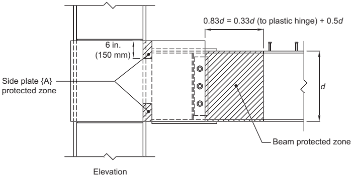
Figure description:
Key Information:
- Subject: Elevation view of a "One-sided connection" in structural engineering.
- Protected Zones:
- Side plate {A} protected zone: Indicated by small hatched areas at the top and bottom of the side plate near the column flange, with a specified vertical dimension of 6 in. (150 mm.
- Beam protected zone: Large hatched area on the beam starting from the side plate.
- Dimensional Formulas:
- Beam protected zone length: (calculated as to plastic hinge + .
- : Total depth of the beam.
- Components: Includes a vertical column, a horizontal beam, side plates, connection bolts, and shear studs on the top flange of the beam.
(a) One-sided connection
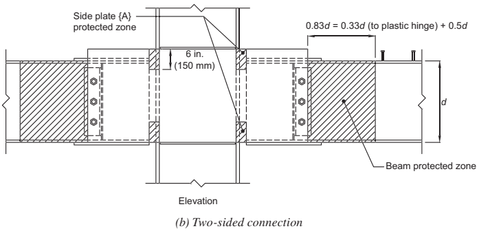
Figure description:
Entities and Key Details:
- Subject: Elevation view of a "Two-sided connection" (Fig. 11.10 for field-welded beam-to-column joints.
- Beam Protected Zone: Represented by the large diagonal-hatched regions extending from the side plates into the beam spans.
- Side Plate {A} Protected Zone: Represented by the smaller diagonal-hatched rectangular regions at the top and bottom edges of the side plates near the column.
- Dimensional Constraints:
- Side Plate Protected Zone Height: 6 in. (150 mm.
- Beam Protected Zone Length: (calculated as to plastic hinge + , where is the depth of the beam.
- Components: Column (vertical, Beams (horizontal, Side plates, and field-welded/bolted connections.
Fig. 11.10. Location of beam and side plate protected zones for the field-welded connection.
- (a) Field-welded connection
(11.4-1a) (11.4-1aM)
- (b) Field-bolted connection
(11.4-1b) (11.4-1bM)
where
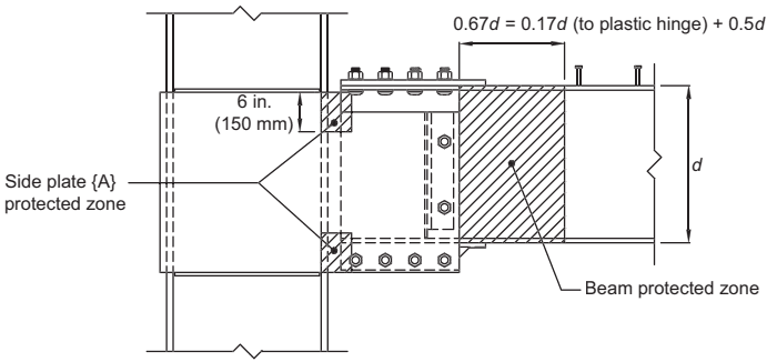
Figure description:
Technical Diagram: One-sided beam-to-column connection
- Key Entities: Column, beam (depth , and bolted side plates.
- Protected Zones:
- Side plate {A} protected zone: Two specific hatched regions at the beam-column interface, each 6 in. (150 mm in height.
- Beam protected zone: A hatched region on the beam web extending from the edge of the connection plate.
- Dimensional Formulas:
- Beam protected zone length = .
- Calculated as: (distance to plastic hinge + .
(a) One-sided connection
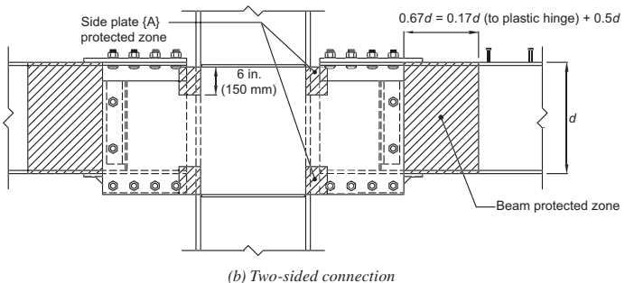
Figure description:
Key Information:
- Component: Two-sided field-bolted structural steel connection.
- Beam Protected Zone: Shaded region on the beam extending a length of from the edge of the side plate connection.
- Length Breakdown: The protected zone length is defined as (distance to plastic hinge + .
- Side Plate {A} Protected Zone: Specific cross-hatched regions at the corners of the side plate connection near the column flange, with a vertical dimension of .
- Variables: represents the depth of the beam.
Fig. 11.11. Location of beam protected zone for the field-bolted connection.
- (2) Panel zones shall conform to the applicable requirements of the AISC Seismic Provisions.
User Note: The column web panel zone strength shall be determined using AISC Specification Section J10.6b.
- (3) Column-beam moment ratios shall be limited as follows:
- (a) For SMF systems, the column-beam moment ratio shall conform to the requirements of the AISCE Seismic Provisions as follows:
- (i) For both uniaxial and biaxial connections, the value of shall be the sum of the projections of the expected flexural strengths of the beam(s) at the plastic hinge locations to the column centerline (Figure 11.13). The expected flexural strength of the beam shall be calculated as:
where
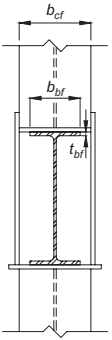
Figure description:
Field-welded connection diagram
- Key Entities:
- Column: Vertical structural member with flange width .
- Beam: I-section member with flange width and flange thickness .
- Continuity Plates: Horizontal plates aligned with the beam flanges.
- Side Plates: Vertical plates attached to the exterior of the column flanges.
- Dimensional Parameters:
- : Column flange width.
- : Beam flange width.
- : Beam flange thickness.
(a) Field-welded connection
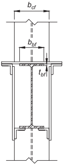
Figure description:
Subject: Structural engineering diagram of a column-beam connection.
Key Dimensions:
- : Width of the column flange.
- : Width of the beam flange.
- : Thickness of the beam flange.
Key Entities:
- Vertical Column: Shown in cross-section with a dashed centerline.
- Beam Flange: Indicated by the hatched horizontal section.
- Connection Components: Side plates and angles connecting the horizontal beam elements to the vertical column.
(b) Field-bolted standard connection (configuration A)
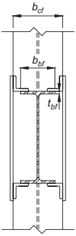
Figure description:
Technical Diagram: Field-bolted Narrow Connection (Configuration B
- Key Entities:
- I-Beam: Centered structural member shown in cross-section.
- Angle Brackets: Four L-shaped components securing the beam flanges.
- Support Structure: Represented by the outer vertical lines (likely a column flange.
- Dimensions:
- : Width of the column flange.
- : Width of the beam flange.
- : Thickness of the beam flange.
- Context: Illustrates a narrow connection where the beam flange width is smaller than the column flange width.
(c) Field-bolted narrow connection (configuration B)
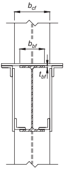
Figure description:
Technical Diagram: Structural Steel Connection
- Key Dimensions:
- : Width of the column flange.
- : Width of the beam flange.
- : Thickness of the beam flange.
- Components:
- Central I-section member.
- Horizontal plate and angle bracket connections.
- Context: Illustrates a field-bolted connection configuration (likely Configuration B or C as per accompanying text.
(d) Field-bolted tuck connection (configuration C)
Fig. 11.12. Geometric compatibility.
be computed as the quantity , where is the shear at the point of theoretical plastic hinging, calculated in accordance with Equation 11.4-3, and is the distance of the assumed point of plastic hinging to the column centerline, which is equal to half the depth of the column plus the extension of the side plates beyond the face of column plus the distance from the end of the side plates to the plastic hinge, .
where
- = distance between plastic hinge locations, in. (mm)
User Note: The load combination of is in conformance with ASCE/SEI 7-22. When using the 2015 International Building Code, a factor of 0.7 must be used in lieu of the factor of 0.15 for (snow) when the roof configuration is such that it does not shed snow off the structure.
- (ii) For the uniaxial connection, the value of shall be the sum of the projections of the nominal flexural strengths of the column, , above and below the connection joint, at the location of theoretical hinge formation in the column (i.e., one-quarter the column depth above and below the extreme fibers of the side plates), to the beam centerline, with a reduction for the axial force in the column (Figure 11.13). The nominal flexural strength of the column shall be computed as:
where
- = equivalent plastic section modulus of column at a distance of column depth from top and bottom edge of side plates, projected to beam centerline, in. , and calculated as:
where
story height, in. (mm)
- (iii) For the biaxial connection, the value of about each axis for the square HSS or built-up box columns shall be taken as:
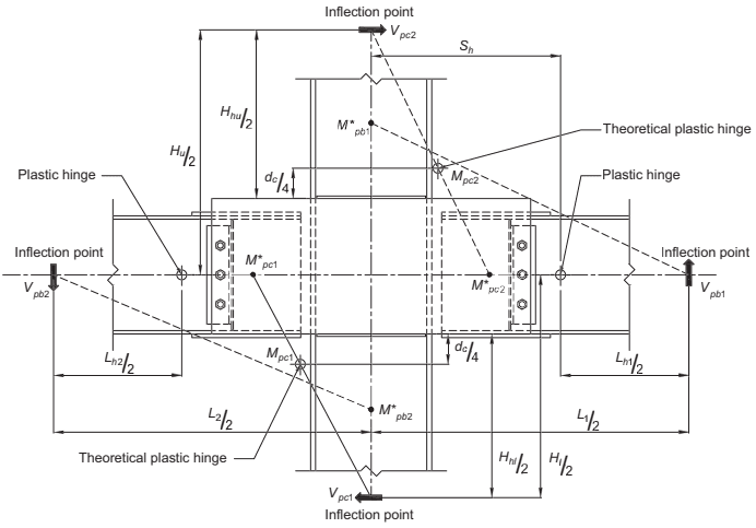
Figure description:
Subject: Structural diagram for calculating column-beam moment ratios at a joint.
Key Entities and Parameters:
- Forces & Moments:
- Column Shears: , at inflection points.
- Beam Shears: , at inflection points.
- Moments: , (column and , (beam at joint boundaries; , at theoretical plastic hinges.
- Dimensions:
- Vertical: Column heights ; joint offset .
- Horizontal: Beam lengths ; hinge offset .
- Structural Points:
- Inflection points: Locations where shear forces are applied on columns and beams.
- Plastic hinges: Identified on both beams flanking the column.
- Theoretical plastic hinges: Specific points used for moment calculations relative to the joint center.
- Contextual Formula: (from provided text.
Fig. 11.13. Force and distance designations for calculation of column-beam moment ratios.
where
- area of concrete in the column, if applicable, in.
- area of the steel column, in.
- actual yield strength of the column at the connection. In the absence of , the expected yield strength of the column may be used, ksi (MPa)
For column sections with unequal properties about both axes, interaction equations based on rational analysis shall be used.
User Note: Guidance for checking columns subject to biaxial bending and axial force is provided in AISC Seismic Provisions Section E3 Commentary.
For the purpose of satisfying strong-column/weak-beam requirements, it shall be permitted to take the actual yield strength of the column material as the specified minimum yield stress and to consider the full composite behavior of the column for axial and flexural loading action if it is filled with concrete.
(b) For IMF systems, the column-beam moment ratio shall conform to the requirements of the AISCE Seismic Provisions.