The design rationale for the SW connection is based upon:
- (a) The IBC (ICC, 2015), the AISC Specification (AISC, 2016b), and the principles of plastic design.
- (b) Results of cyclic qualification tests using beams ranging from W24x94 (W610x140) to W36x393 (W920x585) and columns ranging from W14x176 (W360x262) to W14x550 (W360x818) and W27x307 (W690x457) to W30x235 (W760x350).
- (c) Inelastic finite element analyses to evaluate the stress and strain distributions and buckling modes.
In Step 5, the beam slots are designed to:
- (1) Force the beam shear at the connection to be carried predominately by the beam web.
- (2) Provide a nearly uniform stress and strain distribution horizontally across and vertically through the beam flanges from the column face to the end of the beam web slot.
- (3) Allow plastic beam flange and beam web buckling to occur independently in the region of the beam web slot. This eliminates the lateral-torsional mode of buckling found in beams where the beam web is not slotted.
- (4) Ensure plastic beam flange buckling so that the full plastic moment capacity of the beam is developed:
(C-14.7-1)
In Step 6, a maximum nominal height of the shear plate is used that can accommodate the slot and the weld across the top and bottom of the shear plate. The minimum thickness of the shear plate is based upon the moment increase in the connection from the plastic hinge at the end of the shear plate to the face of the column. Observations from the SW tests have shown that a shear plate equal to or greater than two-thirds the beam web thickness should be used to stabilize the beam web and shear plate from out-of-plane bending to protect the web and plate welds at the column flange. To stabilize the beam web at the column flange, use a minimum shear plate thickness of two-thirds of the beam web thickness but not less than in. (10 mm).
In Step 7, AISC Manual tables may be used to determine the weld size of an eccentrically loaded weld group made from fillet welds for the shear plate based upon the shear plate moment and shear forces as shown in Figure C-14.1.
In Step 8, the shear plate-to-column flange weld must exceed the fillet weld strength of the shear plate eccentrically loaded fillet weld group that resists the increase in the connection moment from the plastic hinge at the end of the shear plate to the column flange.
In Step 9, the bolts are designed for erection purposes and also to clamp the shear plate to the beam web. The effect of this clamping action minimizes the out-of-plane buckling of the plate and beam web near the column flange weldment.
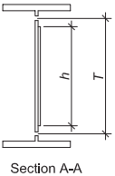
Figure description:
Key Information:
- Drawing Label: Section A-A.
- Key Entities: I-beam section (flanges and web and an attached shear plate.
- Dimensions:
- : Vertical height of the shear plate.
- : Clear distance between the beam flanges (total web depth.
- Structural Context: Illustrates a shear plate clamped to a beam web, a configuration used to minimize out-of-plane buckling near weldments.
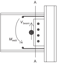
Figure description:
-
Subject: Structural steel beam-to-column connection diagram.
-
Components:
- Horizontal beam connected to a vertical column.
- Vertical shear plate with four circular bolt indicators.
- Section cut line labeled A-A.
-
Forces and Moments:
- : Upward shear force vector.
- : Counter-clockwise bending moment vector.
-
Key Features:
- Shaded circular node at the center of the beam web.
- Horizontal boundary lines with circular endpoints at the top and bottom of the connection region.
-
• The centroid of the SW connection plastic moment is located at the end of the shear plate.
-
• At Section A-A, the beam web moment and shear are resisted by the beam web and the shear plate.
-
• Distribute these forces between the shear plate and the beam web based on the strength distribution.
-
-
Use and to design the shear plate to the beam web weld.
Fig. C-14.1. Beam web—shear-plate force distribution.