The ConXtech® ConXL™ moment connection permits full-strength, fully restrained connection of wide-flange beams to concrete-filled 16 in. (400 mm) square hollow structural section (HSS) or built-up box columns using a high-strength, field-bolted collar assembly. Beams are shop welded to forged flange and web fittings (collar flange assembly) and are field-bolted together through either forged or cast steel column fittings (collar corner assembly) that are shop-welded to the columns. Beams may include reduced beam section (RBS) cutouts if necessary to meet strong-column/ weak-beam criteria. ConXL connections may be used to provide moment connections to columns in orthogonal frames. All moment beams connecting to a ConXL node (intersection of moment beams and column) must be of the same nominal depth.
Figure 10.1 shows the connection geometry and major connection components. Each ConXL collar assembly is made up of either forged or cast collar corners and forged collar flanges. At each ConXL node there are four collar corner assemblies (Figure 10.2)—one at each corner of the square built-up or HSS column. Each ConXL node also contains four collar flange assemblies (Figure 10.3)—one for each face of the square column. Each collar flange assembly can contain the end of a moment beam that is shop welded to the collar flange assembly. The combination of collar corner assemblies, collar flange assemblies, and a square concrete-filled column create the ConXL node.
Figure 10.2 shows the collar corner assemblies. The collar corner assembly is made up of a collar corner top (CCT) piece; a collar corner bottom (CCB) piece; and for beam depths greater than 18 in. (450 mm), a collar corner middle (CCM) piece. The CCT, CCB, and CCM are partial-joint-penetration (PJP) groove welded together to create the collar corner assembly; they are then shop fillet-welded to the corners of the square column.
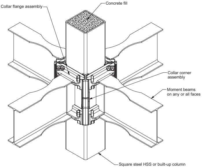
Figure description:
Key Information: Assembled ConXL Moment Connection
- Central Support: Square steel HSS (Hollow Structural Section or built-up column filled with concrete.
- Beam Attachment: Moment beams can be connected to any or all four faces of the column.
- Connection Components:
- Collar flange assembly: Attaches the beam flanges to the connection.
- Collar corner assembly: Secures the connection at the column corners.
- Context: Structural diagram of a specialized moment-resisting beam-to-column connection (ConXL.
Fig. 10.1. Assembled ConXL moment connection.
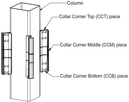
Figure description:
Technical Diagram: Column with Collar Corner Assemblies
- Core Entity: Square hollow structural column.
- Key Components: Collar corner assemblies mounted on the exterior corners of the column.
- Collar Assembly Parts:
- Collar Corner Top (CCT piece: Upper component featuring pre-drilled bolt holes.
- Collar Corner Middle (CCM piece: Central component of the assembly.
- Collar Corner Bottom (CCB piece: Lower component featuring pre-drilled bolt holes.
Fig. 10.2. Column with attached collar corner assemblies.
Figure 10.3 shows the collar flange assembly. Each collar flange assembly is made up of a collar flange top (CFT), collar flange bottom (CFB), and a collar web extension (CWX).
If a beam at the node requires a moment connection, the CFT (or CFB) is aligned with and shop welded to the top (or bottom) flange of the beam.
Moment-connected beam webs are also shop welded to the CWX. If a beam at the node does not require a moment connection, the size of the CWX remains unchanged and a single-plate shear connection is shop-welded to the CWX to accommodate a non-moment-connected beam that does not need to match the nominal depth of the moment-connected beam(s).
If no beams exist on a node at a particular column face, the CFT and CFB are aligned at the nominal depth of the moment beam and the CWX shall be permitted to be optionally omitted.
Section 10.8 contains drawings indicating the dimensions of individual pieces.
Columns are delivered to the job site with the collar corner assemblies shop welded to the column at the proper floor framing locations. Beams are delivered to the job site with the collar flange assemblies shop welded to the ends of the beams. During frame erection the collar flange assemblies with or without beams are lowered into the column collar corner assemblies. When all four faces of the column are filled with collar flanges, the collar bolts are inserted and pretensioned, effectively clamping and
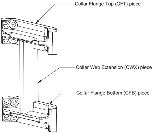
Figure description:
Key Components of Figure 10.3: Collar Flange Assembly
- Collar Flange Top (CFT piece: The upper horizontal component with pre-drilled bolt holes.
- Collar Web Extension (CWX piece: The vertical connecting plate between the top and bottom flange pieces.
- Collar Flange Bottom (CFB piece: The lower horizontal component, mirroring the CFT, also featuring pre-drilled bolt holes.
Fig. 10.3. Collar flange assembly.
compressing the collar flange assemblies around the collar corner assemblies and square column.
Beam flange flexural forces in moment beams are transferred to the collar flange assemblies via CJP groove welds. Collar flanges transfer compressive beam flange forces to the collar corners through flexure of the collar flange and direct bearing onto the collar corners. The collar flange transfers beam flange tensile forces in flexure to the pretensioned collar bolts. The collar bolts transfer these forces in tension through the orthogonal collar flanges, which then transfer the forces through the rear collar bolts attached to the collar flange on the opposite face of the column. These combined forces are then transferred to the column walls through a combination of bearing and the fillet welds attaching the collar corners to the column. Finally, a portion of these forces are transferred to the concrete fill, which is in direct contact with the column walls.
The behavior of this connection is controlled by flexural hinging of the beams adjacent to the collar assembly. When RBS cutouts are provided, yielding and plastic hinge formation primarily occur within the reduced beam section.