Figures 15.3 through 15.7 define the symbols for various plate thicknesses, dimensions, weld sizes, and bolt quantities that are pertinent to the connection and discussed in the design steps.
15.5.1 Welds
The welds designated [W1] and [W2] in Figure 15.3 shall be held back one weld size. When [W2] is made to an HSS column, the weld holdback shall be measured from
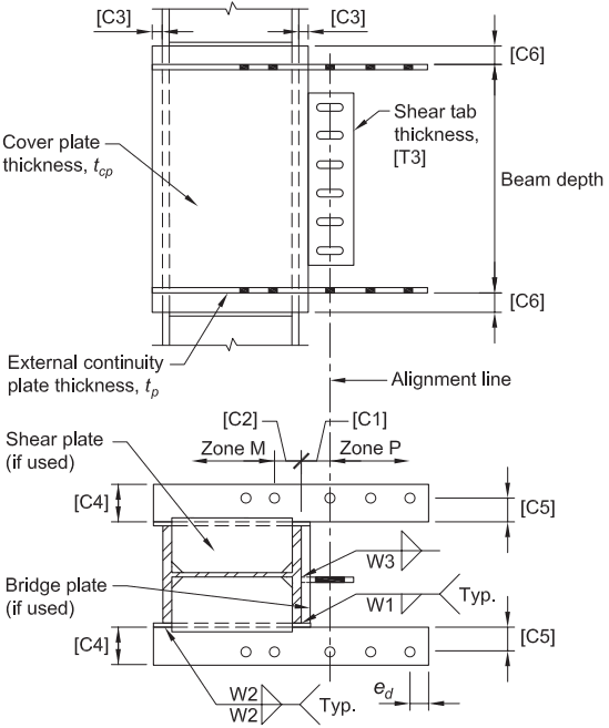
Figure description:
Fig. 15.3. Column Assembly Detail
Key Entities and Dimensions:
- Components:
- Column: Main vertical structure with internal reinforcement [C3.
- Cover Plate: Side reinforcement with thickness .
- External Continuity Plates: Top and bottom plates with thickness and vertical spacing [C6.
- Shear Tab: Vertical attachment for beam connection with thickness [T3.
- Shear Plate / Bridge Plate: Internal connection components (indicated "if used".
- Dimensional Parameters:
- Beam Depth: Vertical distance between continuity plates.
- Alignment Line: Vertical reference axis passing through the shear tab and plates.
- Zones: Zone M and Zone P divided by the alignment line.
- Plate Dimensions:
- [C1, [C2: Horizontal offsets from alignment line.
- [C4, [C5: Horizontal plate widths/offsets.
- : Spacing between fastener holes.
- Weld Specifications:
- W1, W2, W3: Specific fillet and groove weld symbols indicated as "Typ." (typical.
Fig. 15.3. Column assembly detail.
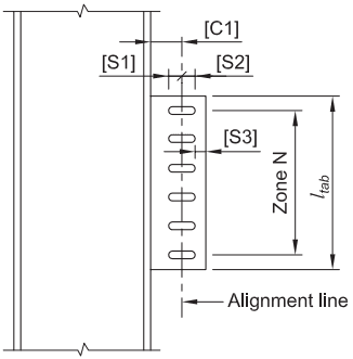
Figure description:
Entity: Single-plate shear connection detail
Key Components & Dimensions:
- Column: Vertical structural member to which the plate is attached.
- Shear Plate (Tab: Rectangular plate with six slotted holes.
- Alignment Line: Vertical centerline passing through the slotted holes.
- [C1: Horizontal distance from column face to the alignment line.
- [S1, [S2, [S3: Horizontal dimensional tolerances or offsets for the slots relative to the column face and alignment line.
- Zone N: Vertical region encompassing the central four slots.
- : Total vertical length of the shear plate.
Fig. 15.4. Single-plate shear connection detail.
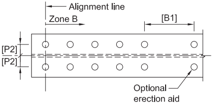
Figure description:
Subject: Technical diagram of a Top Flange.
Key Components and Labels:
- Hole Layout: Two parallel rows of circular holes arranged symmetrically around a central horizontal axis.
- Alignment Line: A vertical reference line passing through the center of the first pair of holes.
- Zone B: Area extending horizontally to the right from the alignment line.
- [P2: Vertical dimension indicating the distance from the centerline to each row of holes.
- [B1: Horizontal dimension representing the spacing between specific hole pairs.
- Optional Erection Aid: Designation for the final pair of holes on the right side.
Top Flange
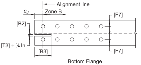
Figure description:
Key Entities and Details: Fig. 15.5. Beam end detail
- Subject: Structural diagram showing a beam end detail with top and bottom flanges.
- Dimensions and Labels:
- : Distance from the beam edge to the first set of vertical holes.
- [B2: Vertical gap width of the central notch.
- [B3: Horizontal depth of the central notch.
- [T3 + ¼ in.: Vertical distance from the center line to the bottom edge of the notch.
- [F7: Vertical spacing between the center line and the bolt holes on both top and bottom sections.
- Structural Features:
- Alignment line: Vertical reference line passing through the first column of holes.
- Zone B: Area indicated to the right of the alignment line.
- Bolt Holes: Two horizontal rows of five circular holes (ten total.
- Notch: A narrow horizontal cutout at the beam end along the center line.
Fig. 15.5. Beam end detail.
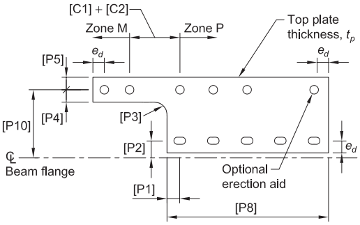
Figure description:
Subject: Fig. 15.6, Top plate detail for a beam end connection.
Key Components & Features:
- Top Plate: Specified with thickness .
- Zones: Divided into Zone M (narrower left section and Zone P (wider right section, separated by distance .))
- Holes:
- Top row: Circular holes, including a specific optional erection aid hole.
- Bottom row: Horizontal slotted holes.
- Reference Line: Beam flange centerline (CL.
Dimensional Parameters:
- Vertical: (CL to top holes, (CL to bottom holes, (hole spacing, (top edge distance.
- Horizontal: (width of wider section, (edge to first slot, (general edge distances.
- Geometry: indicates the internal corner radius.
Fig. 15.6. Top plate detail.
the end of the workable flat. [W1] is omitted when the walls of an HSS or box column function as sole cover plates.
15.5.2 Bolts
- (1) Bolts shall be arranged symmetrically about the axis of the beam and shall be limited to two lines of bolts in each beam flange.
- (2) Standard holes shall be used in the beam flanges and in the external continuity plates. Holes in the top plates and fuse plate shall be oversized except for the short-slotted holes indicated in Figure 15.6.
- (3) Bolt holes in beam flanges and plates shall be made by drilling, sub-punching and reaming, laser cutting, plasma cutting, or water-jet cutting.
- (4) All bolts shall be installed as pretensioned high-strength bolts.
- (5) Bolts shall be ASTM F3125/F3125M Grades A325, A325M, A490, A490M, F1852, or F2280 assemblies. Threads shall be excluded from the shear plane. The bolt diameter shall not exceed 1¼ in. (30 mm).
- (6) Faying surfaces shall have a Class A slip coefficient but shall not have a slip coefficient greater than 0.50 (Class B).
- (7) A maximum gap of 1/4 in. (6 mm) between the top plate and the external continuity plate or beam flange and between the fuse plate and the external continuity plate or beam flange is permitted and may be closed through deformation of the plates. Shim plates with a maximum overall thickness of 1/4 in. (6 mm) are permitted.
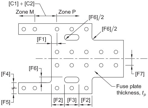
Figure description:
Key Information: Fuse Plate Detail
- Primary Zones:
- Zone M: Leftmost section of the plate.
- Zone P: Central/transition section.
- Dimensions and Spacing Labels:
- [C1 + [C2: Distance between Zone M and Zone P.
- [F1: Horizontal offset between hole sets.
- [F2, [F3: Horizontal intervals for specific hole columns in the central body.
- [F4, [F5: Vertical hole positioning from edges and between centers.
- [F6, [F6/2: Vertical spacing and radius/offset indicators for curved edges and oval slots.
- [F7: Vertical offset from the horizontal centerline.
- Physical Features:
- Grid of circular holes across the plate.
- Two central elongated/oval slots.
- : Label indicating fuse plate thickness.
- Symmetrical layout relative to a horizontal centerline.
Fig. 15.7. Fuse plate detail.
15.5.3 Beam Slot
Beam bottom flanges are permitted to be slotted in accordance with Figure 15.5. The distance between the edge of the bolt holes and the cut shall be at least 3/8 in. (10 mm).
User Note: The purpose of the slot in the beam bottom flange is to permit the beam to drop down past the single-plate shear connection during erection.
15.5.4 Plate Fabrication and Repair
The roughness of all thermally cut surfaces shall be no greater than an ANSI surface roughness of 1000 μin. (25 μm). Gouges and notches in the protected zone shall be repaired in accordance with AWS D1.8/D1.8M.