11.3.1 Beam Limitations
A wide range of beam sizes, including both rolled and built-up wide-flange and HSS beams, has been tested with the SidePlate moment connection, in both uniaxial and biaxial conditions. For the field-welded connection, the smallest beam size was a W18x35 (W460x52) and the heaviest a W40x297 (W1000x443). For the field-bolted connection, the smallest beam size was a W21x73 (W530x109), and the largest beam size was a W40x397 (W1000x591). The deepest beam tested was a W44x290 (W1100x433) with a depth of 43.6 in. (1110 mm). Beam compactness ratios have varied from that of a W18x35 (W460x52) with to a with . For HSS beam members, tests have focused on small members such as the HSS7x4x1/2 (HSS177.8x101.6x12.7) having ratios of and . As a result of these testing programs, critical ultimate strength design parameters for the design and detailing of the SidePlate moment connection systems have been developed for general project use. These requirements and design limits are the result of a detailed assessment of actual performance data coupled with independent physical validation testing and/or corroborative analytical testing of full-scale test specimens using nonlinear FEA. It was the judgment of the CPRP that the maximum beam depth and weight of the SidePlate moment connection would be limited to the nominal beam depth and approximate weight of the sections tested, as has been the case for most other connections.
Because the behavior and overall ductility of the SidePlate moment connection systems is defined by the plastic rotational capacity of the beam, the limit state for the SidePlate moment connection system is ultimately the failure of the beam flange, away from the connection. Therefore, the limit of the hinge-to-hinge span-to-depth ratio of the beam, , is based on the demonstrated rotational capacity of the beam.
As an example, for test specimen 3 tested at Lehigh University (Hodgson et al., 2010c), the W40×294 (W1000×438) beam connected to the W36×395 (W920×588) column reached two full cycles at 0.06 rad of rotation (measured at the centerline of the column), which is significantly higher than the performance threshold of one cycle at 0.04 rad of rotation required for successful qualification testing by the AISC Seismic Provisions. Most of the rotation at that amplitude came from the beam rotation at the plastic hinge. At this same 0.06 rad measured at the column centerline, the measured rotation at the beam hinge was between 0.085 and 0.09 rad [see Figure C-11.2(a)]. The tested half-span was 14.5 ft (4.4 m), which represents a frame span of 29 ft (8.8 m) and an ratio of 5.5. Assuming that of the frame system's rotation comes from the beam's hinge rotation (a conservative assumption because it ignores the rotational contributions of the column and connection elements), it is possible to calculate a minimum span at which the frame drift requirement of one cycle at 0.04 rad is maintained, while the beam reaches a maximum of 0.085 rad of rotation. This calculation gives a minimum span of 20 ft (6.1 m) and an ratio of 3. Making this same calculation for the tests of the (W920x223) beam [Minh Huynh and Uang, 2012; Figure C-11.2(b)], using an average maximum beam rotation of 0.08 rad of rotation, gives a minimum span of 18 ft, 10 in. (5.7 m) and an ratio of 3.2. Given that there will be variations in the performance of wideflange beams due to local effects such as flange buckling, it is reasonable to set the lower bound ratio for the SidePlate field-welded moment connection system at 4.5 for SMF and 3.0 for IMF, regardless of beam compactness. It should be noted that the minimum ratio of 4.5 (where is measured from the centerline of the beam's plastic hinges) typically equates to 6.7 as measured from the face of column to face of column when the typical side plate extension (shown as "Side plate extension" in Figure 11.9) from face of column is used. The 6.7 ratio, which is slightly less than the 7.0 for other SMF moment connections, allows the potential for a deeper beam to be used in a shorter bay than other SMF moment connections. The field-bolted testing program at UCSD (Mashayekh and Uang, 2016; Reynolds and Uang, 2017) showed that the field-bolted connections sustained approximately more story drift, so it is reasonable to set the lower bound ratio for the SidePlate field-bolted moment connection at 4.0 for SMF and 3 for IMF regardless of beam compactness [see Figure C-11.2(c) for the measured rotation of the field-bolted (W1000x314) beam and Figure C-11.2(d) for the measured rotation of the field-bolted (W1000x591) beam at the hinge location]. All momentconnected beams are required to satisfy the width-to-thickness requirements of AISCEismic Provisions Sections E2 and E3.
Required lateral bracing of the beam follows the AISc Seismic Provisions. However, due to the significant lateral and torsional restraint provided by the side plates {A} as observed in all full-scale tests, for calculation purposes, the unbraced length of the beam is taken as the distance between the respective ends of each side plate {A} extension (see Figures 11.14 through 11.21 for depictions of the alphabetical designations). As determined by the full-scale tests, no additional lateral bracing is required at or near the plastic beam hinge location.
Lateral bracing of columns in accordance with AISC Seismic Provisions Section E3.4c.1 is not a requirement if the beam is sufficiently braced at the top beam flange (e.g., with a deck or slab). Sufficient bracing of the beam can be attained by either continuous bracing of the beam top flange by slab on deck or by meeting the requirements of AISC Seismic Provisions Section D1.2b. The substantiation for not using direct bracing is twofold. One is that none of the qualifying tests had any additional direct column bracing at the level of the top or bottom beam flanges, and the column tree did not exhibit any sign of torsional twisting, even for deep columns. This was due to the significant lateral and torsional restraint provided by side plates {A} that indirectly braced the column. This is in accordance with AISC Seismic Provisions Section E3.4c.1, where the indirect stability bracing is permitted if substantiated. Second, an internal numerical study was conducted by SidePlate Systems to demonstrate that the side plates {A} provide adequate indirect stability bracing and that the connection does not need additional lateral bracing for column stability.
Test Specimen 3 (W40x294 Beam to W36x395 Column)
Moment vs Rotation at Hinge
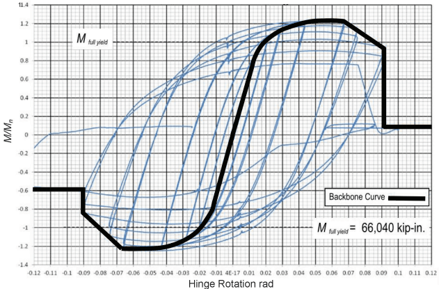
Figure description:
Hysteretic Loop: vs Hinge Rotation
Legend
- Backbone Curve — color: black; symbol: Thick solid line
Annotations
- (horizontal_line - position: y = 1.0)
- (horizontal_line - position: y = -1.0)
- kip-in. (text_label - position: x = 0.08, y = -1.0)
| Hinge Rotation (rad) | (Backbone Curve) |
|---|---|
| -0.12 | -0.58 |
| -0.092 | -0.58 |
| -0.092 | -0.85 |
| -0.08 | -1.05 |
| -0.068 | -1.23 |
| -0.04 | -1.21 |
| -0.02 | -1.05 |
| -0.01 | -0.85 |
| -0.005 | -0.50 |
| 0 | 0 |
| 0.005 | 0.50 |
| 0.01 | 0.85 |
| 0.02 | 1.05 |
| 0.04 | 1.21 |
| 0.068 | 1.25 |
| 0.08 | 1.15 |
| 0.092 | 0.95 |
| 0.092 | 0.08 |
| 0.12 | 0.08 |
Notes: The chart shows cyclic hysteretic behavior (blue lines bounded by a defined backbone curve (thick black line. The y-axis represents normalized moment () and the x-axis represents hinge rotation in radians. The top y-axis label appears to be 1.4, though it is slightly obscured.))
(a) W40x294 (W1000x438) beam (field welded)
Tests UCSD 1 and UCSD 2 (W36x150 Beam to W36x231 Column)
Moment vs Rotation at Hinge
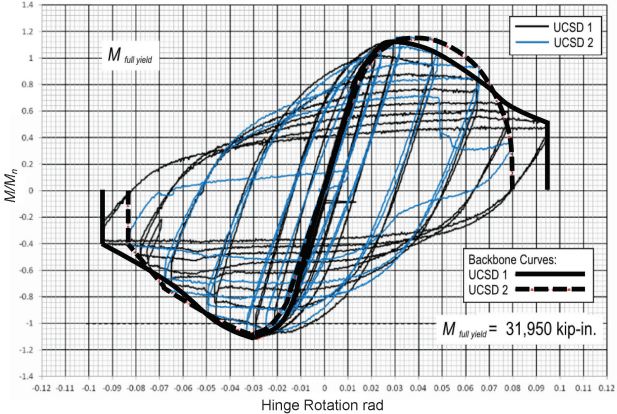
Figure description:
Normalized Moment vs. Hinge Rotation
Normalized Moment (M/M_n vs. Hinge Rotation
Legend
- UCSD 1 (hysteresis — color: black; symbol: solid line
- UCSD 2 (hysteresis — color: blue; symbol: solid line
- Backbone Curves: UCSD 1 — color: black; symbol: thick solid line
- Backbone Curves: UCSD 2 — color: black/red; symbol: thick dashed line
Annotations
- M_full yield (text_label - position: (-0.06, 1.1))
- M_full yield = 31,950 kip-in. (text_label - position: (0.08, -1.05))
- Horizontal reference line at -1.0 (horizontal_line - position: y = -1.0)
| Hinge Rotation (rad) | UCSD 1 Backbone (M/M_n) | UCSD 2 Backbone (M/M_n) |
|---|---|---|
| -0.095 | 0.00 | null |
| -0.095 | -0.40 | null |
| -0.090 | -0.41 | null |
| -0.085 | null | 0.00 |
| -0.085 | null | -0.40 |
| -0.080 | -0.52 | -0.55 |
| -0.070 | -0.65 | -0.65 |
| -0.060 | -0.78 | -0.75 |
| -0.050 | -0.90 | -0.85 |
| -0.040 | -1.05 | -1.05 |
| -0.030 | -1.12 | -1.10 |
| -0.020 | -0.90 | -0.95 |
| -0.010 | -0.40 | -0.50 |
| 0.000 | 0.00 | 0.00 |
| 0.010 | 0.40 | 0.50 |
| 0.020 | 0.95 | 1.00 |
| 0.030 | 1.10 | 1.13 |
| 0.040 | 1.12 | 1.15 |
| 0.050 | 1.05 | 1.12 |
| 0.060 | 0.95 | 1.05 |
| 0.070 | 0.82 | 0.85 |
| 0.080 | 0.70 | 0.30 |
| 0.080 | null | 0.00 |
| 0.090 | 0.58 | null |
| 0.095 | 0.52 | null |
| 0.095 | 0.00 | null |
Notes: The plot displays hysteresis loops and their envelopes (backbone curves for two experimental tests, UCSD 1 and UCSD 2. The backbone curves are highlighted with thicker lines. The table contains estimated values for the backbone curves based on the chart's grid.)
(b) W36x150 (W920x223) beam (field welded)
Fig. C-11.2. (a and b) SidePlate moment frame tests— backbone curves. (Measured at the beam hinge location.)
Test Specimen U1 (W40x211 Beam to W36x282 Column Config. A)
Moment vs Rotation at Hinge
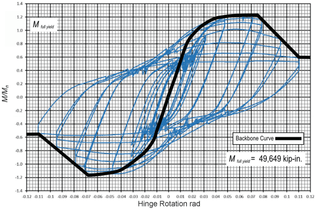
Figure description:
Normalized Moment vs. Hinge Rotation
Moment-Rotation Hysteresis and Backbone Curve
Legend
- Backbone Curve — color: black; symbol: Thick solid line
- Hysteresis Loops — color: blue; symbol: Thin solid lines
Annotations
- M full yield (text_label - position: top left area, y ≈ 1.1, x ≈ -0.1)
- M full yield = 49,649 kip-in. (text_label - position: bottom right area, y ≈ -0.85, x ≈ 0.09)
| Hinge Rotation (rad) | M/Mn (Backbone Curve) |
|---|---|
| -0.12 | -0.55 |
| -0.11 | -0.55 |
| -0.10 | -0.73 |
| -0.09 | -0.88 |
| -0.08 | -1.03 |
| -0.07 | -1.16 |
| -0.06 | -1.15 |
| -0.05 | -1.13 |
| -0.04 | -1.10 |
| -0.03 | -0.98 |
| -0.02 | -0.83 |
| -0.012 | -0.60 |
| 0.015 | 0.85 |
| 0.02 | 0.95 |
| 0.03 | 1.07 |
| 0.04 | 1.15 |
| 0.05 | 1.21 |
| 0.06 | 1.23 |
| 0.07 | 1.24 |
| 0.075 | 1.24 |
| 0.08 | 1.16 |
| 0.09 | 1.00 |
| 0.10 | 0.80 |
| 0.11 | 0.60 |
| 0.12 | 0.60 |
Notes: The chart shows a series of blue hysteresis loops representing cyclic loading behavior, with a thick black backbone curve outlining the envelope of the response. The vertical axis represents the normalized moment (M/Mn, and the horizontal axis represents hinge rotation in radians.)
(c) W40x211 (W1000x314) beam (field bolted)
Test Specimen U5 (W40x397 Beam to BU30x30x2 Column Config. A) Moment vs Rotation at Hinge
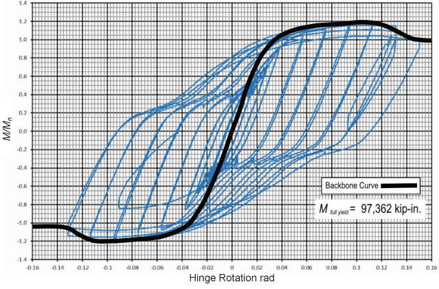
Figure description:
Normalized Moment vs. Hinge Rotation Hysteresis
Legend
- Backbone Curve — color: black; symbol: Thick solid line
- Experimental Cyclic Data — color: blue; symbol: Thin solid line
Annotations
- M_{full yield} = 97,362 kip-in. (text_label - position: x = 0.12, y = -0.8)
| Hinge Rotation (rad) | M/Mn (Backbone Curve) |
|---|---|
| -0.16 | -1.04 |
| -0.15 | -1.04 |
| -0.14 | -1.04 |
| -0.13 | -1.08 |
| -0.12 | -1.16 |
| -0.11 | -1.21 |
| -0.10 | -1.21 |
| -0.09 | -1.20 |
| -0.08 | -1.19 |
| -0.07 | -1.17 |
| -0.06 | -1.16 |
| -0.05 | -1.14 |
| -0.04 | -1.08 |
| -0.03 | -0.92 |
| -0.02 | -0.68 |
| -0.01 | -0.34 |
| 0.00 | 0.00 |
| 0.01 | 0.34 |
| 0.02 | 0.70 |
| 0.03 | 0.94 |
| 0.04 | 1.06 |
| 0.05 | 1.12 |
| 0.06 | 1.14 |
| 0.07 | 1.16 |
| 0.08 | 1.17 |
| 0.09 | 1.18 |
| 0.10 | 1.19 |
| 0.11 | 1.18 |
| 0.12 | 1.16 |
| 0.13 | 1.10 |
| 0.14 | 1.04 |
| 0.15 | 1.00 |
| 0.16 | 0.99 |
Notes: The chart shows the hysteresis loops for hinge rotation (rad versus normalized moment (M/Mn. The thick black line represents the backbone curve, which follows the envelope of the cyclic response.))
(d) W40x397 beam (field-bolted)
Fig. C-11.2. (c and d) SidePlate moment frame tests— backbone curves. (Measured at the beam hinge location.)
The protected zone is defined as shown in Figures 11.10 and 11.11 and extends from the end of the side plate {A} to half the beam depth beyond the plastic hinge location, which is located at one-third the beam depth in the field-welded connection and one-sixth the beam depth in the field-bolted connection beyond the end of the side plate {A} due to the cover plate {B} or angle {H} extensions. This definition is based on test observations that indicate yielding typically does not extend past 83% and 67% of the depth of the beam from the end of the side plate {A} in the field-welded and field-bolted connections, respectively.
11.3.2 Column Limitations
SidePlate® moment connections have been tested with W14 (W360); W16 (W410); W30 (W760); W33 (W840) built-up I-sections; W36 (W840); built-up box sections of 30×30×2 (750×750×50) and 27×27×2½ (680×680×65); and hollow structural sections (HSS), including HSS14×14×7/8 (HSS355.6×355.6×22), HSS18×18×3/4 (HSS457.2×457.2.6×19), and HSS20×20×7/8 (HSS508×508×22). Note that when using HSS and built-up box columns, the side plates {A} transfer the loads to the column in the same way as with wide-flange columns. The only difference is that the horizontal shear component at the top and bottom of the side plates {A} now transfer that horizontal shear directly into the faces of the HSS and built-up box column using a shop fillet weld; thus, an internal horizontal shear plate {D} or stiffener plate is not required. This was verified with the execution of various tests, including a test with a W40×397 (W1000×591) beam and a 30×30×2 (760×760×50) built-up box column, as well as a W27×102 (W690×152) beam and HSS20×20×7/8 (HSS508×508×22) column, both without internal horizontal shear plates {D} or stiffeners (continuity plates). As such, built-up box columns are prequalified as long as they meet all applicable requirements of the AISC Seismic Provisions, with the exceptions mentioned here. There are no internal stiffener or continuity plates within the column, and there are no requirements that the columns be filled with concrete for either SMF or IMF applications. Also no CJP groove welds will be required within a zone extending from 12 in. (300 mm) above the upper beam flange to 12 in. (300 mm) below the lower beam flange, flange, and web plates of boxed wide-flange columns in SidePlate moment connections with built-up box columns. Note: In some blast or other seismic loading applications, there may be advantages to filling the HSS or built-box columns with concrete to strengthen the column.
In 2015, SidePlate Systems conducted two tests with HSS columns as part of the testing program for expanding its prequalification to field-bolted connections (Mashayekh and Uang, 2016). This configuration is also referred to as the SidePlate PLUS Connection. The secondary purpose of these tests was the inclusion of HSS columns with the width-to-thickness ratio of up to 21 in SidePlate moment connections. It was believed that the width-to-thickness ratio of the walls of HSS columns is a function of local buckling of the walls of the HSS shape in addition to the connection itself. Therefore, it was decided to apply a substantial axial load on the columns (40% nominal axial strength of the column) to test and relax the width-to-thickness limit for SidePlate moment connections. The columns performed very well, and there was no yielding/buckling on the face of HSS columns. As a result of two full-scale physical tests and numerous numerical studies, it was confirmed that the width-to-thickness limit of HSS columns in SidePlate moment connections can be increased to 21 as long as the axial load in the column stays below of the nominal axial strength of the column-that is, . The HSS column in the tests complied with ASTM A500/A500M Grade C. The columns performed very well; there were no issues regarding the performance of the column. However, it was decided to limit the HSS column to ASTM A1085/A1085M per the CPRP's recommendation.
The behavior of SidePlate moment connections with cruciform columns is similar to uniaxial one- and two-sided moment connection configurations because the ultimate failure mechanism remains in the beam. Successful tests have been conducted on SidePlate moment connections with cruciform columns using W36 (W920) shapes with rolled or built-up structural tees.
In 2018, cyclic testing of five full-scale field-bolted SidePlate steel moment connections was conducted at UCSD (Reynolds and Uang, 2018) to evaluate their performance. Four of the specimens (B1, B2, B3, and B4) were biaxially loaded, while Specimen B1a was uniaxially loaded. Each of the biaxially loaded specimens underwent two stages of loading. The first stage of loading was the monotonic loading of the transverse beams to a predefined load to develop the probable maximum moment at the column face in these beams. The second stage of loading consisted of the standard cyclic loading sequence as specified in the 2016 AISC Seismic Provisions applied to the primary beam. The uniaxially loaded specimen was only subjected to the AISC Seismic Provisions cyclic loading protocol. Specimen B2 was the first specimen tested and consisted of a built-up box column with transverse beams and a primary beam. Specimen B1 was the second specimen tested and consisted of an HSS column with transverse beams and a primary beam. The remaining tests reused the same side plates {A}, column, and transverse beams from Specimen B1. Specimens B3 and B4 used a built-up I section 33 in. (840 mm) deep with a nominal weight of 105 lb/ ft (160 kg/m). The newly developed tuck configuration (configuration C) was used for Tests B3 and B4 where the bottom angles were inverted in comparison with the standard configuration and connected to the interior face of the beam bottom flange. Specimens B1a, B3, and B4 did not use vertical shear elements. These specimens utilized ASTM A992/A992M, ASTM A572/A572M Grade 50 (Grade 345), and ASTM A500/A500M Grade C steel for the W-shapes, plates, and HSS, respectively. ASTM F3148 and ASTM F3125/F3125M Grade F2280 high-strength bolts were used in the connections. Specimen B2 ultimately failed by fracture of the beam bottom flange after completing the 5% drift cycles. Testing of Specimens B1 and B1a was stopped after achieving 7% and 6% drift, respectively, to preserve the column for future tests. The primary beams of Specimens B1 and B1a were identical except that Specimen B1a did not utilize vertical shear elements. The performance of the two beams was comparable and no degradation in the performance was observed due to the elimination of the vertical shear element.
For SMF systems, the column bracing requirements of AISC Seismic Provisions Section E3.4c.1 are satisfied when a lateral brace is located at or near the intersection of the frame beams and the column. Note: Full-scale tests have demonstrated that without any additional lateral bracing the full-depth side plates {A} provide the required indirect lateral bracing of the column flanges through the side plate {A}-to-column flange welds and the connection elements that connect the column web to the side plates {A}. Therefore, no additional direct lateral bracing of the column flanges is required.
11.3.3 Connection Limitations
All test specimens have used ASTM A572/A572M Grade 50 (Grade 345) plate material, and connection plates are required to comply with this material standard. There are two exceptions. The first exception is for thick plates used in the side plate interlock assembly, where material is conservatively specified to provide improved levels of notch-toughness to accommodate potentially higher toughness demands associated with the re-entrant corners in the slots. The second exception is for the vertical shear element, where ASTM A36/A36M material is permitted, based on the low stresses in this element.
Nonlinear finite element parametric modeling of side plate extensions in the range of to have demonstrated similar overall connection and beam behavior when compared to the results of full-scale tests.
Because there is a controlled level of plasticity within the design of the two side plates {A}, the side plate {A} protected zones have been designated based upon test observations as indicated in Figures 11.10 and 11.11, respectively. It should be noted that a more conservative design methodology is used for the design of the side plates {A} of the field-bolted configuration, which results in even less yielding in the critical section of the side plates {A}. However, it was decided for consistency to assign similar protected zones for both the field-welded and the field-bolted connections.