Table C-2.1 summarizes the prequalified beam sections for each connection, and Table C-2.2 summarizes the prequalified column sections for each connection. Each connection imposes additional limitations on beam and column sections that may include size, weight per foot, and other limitations.
2.3.2 Built-up Members
2.3.2b Built-up Columns
Four built-up column cross-section shapes are covered by this standard. These are illustrated in Figure C-2.1 and include the following:
- (1) I-shaped welded columns that resemble standard rolled wide-flange shapes in cross-section shape and profile.
| Connection | Prequalified Beam Section | ||
|---|---|---|---|
| Rolled Wide-Flange | Built-up I-Shape | HSS | |
| RBS (Chapter 5) | |||
| BUEEP and BSEEP (Chapter 6) | |||
| BFP (Chapter 7) | |||
| WUF-W (Chapter 8) | |||
| CBB (Chapter 9) | |||
| ConXL (Chapter 10) | √ | √ | |
| Simpson Strong-Tie Strong Frame (Chapter 12) | |||
| Double-Tee (Chapter 13) | |||
| SW (Chapter 14) | |||
| DuraFuse Frames (Chapter 15) | |||
| SidePlate (Chapter 11) | √ | √ | √ |
| Prequalified Column Sections | ||||||
|---|---|---|---|---|---|---|
| Prequalified Column Section | ||||||
| Connection | Rolled Wide- Flange | Built-up I-Shape | Boxed Wide- Flange | Built-up Box | Flanged Cruci form | HSS |
| RBS (Chapter 5) BFP (Chapter 7) WUF-W (Chapter 8) CBB (Chapter 9) Slotted Web (Chapter 14) | √ | √ | √ | √ | √ | |
| ConXL (Chapter 10) | √ | √ | ||||
| BUEEP and BSEEP (Chapter 6) Simpson Strong-Tie Strong- Frame (Chapter 12) Double-Tee (Chapter 13) | √ | √ | √ | |||
| SidePlate (Chapter 11) DuraFuse Frames (Chapter 15) | √ | √ | √ | √ | √ | √ |
- (2) Cruciform W-shape columns, fabricated by splitting a wide-flange section in half and welding the webs on either side of the web of an unsplit wide-flange section at its mid-depth to form a cruciform shape, each outstanding leg of which terminates in a rectangular flange.
- (3) Box columns, fabricated by welding four plates together to form a closed box-shaped cross section.
- (4) Boxed W-shape columns constructed by adding side plates to the sides of an I-shaped cross section.
The preponderance of connection tests reviewed as the basis for prequalifications contained in this standard consisted of rolled wide-flange beams connected to the flanges of rolled wide-flange columns. A limited number of tests of connections of wide-flange beams to built-up box-section columns were also reviewed (Anderson and Linderman, 1991; Kim et al., 2008).
The flanged cruciform column and boxed wide-flange columns have not specifically been tested. However, it was the judgment of the CPRP that as long as such column sections met the limitations for I-shaped sections and box-shaped sections, respectively, and connection assemblies are designed to ensure that most inelastic behavior occurred within the beam as opposed to the column, the behavior of assemblies employing these sections would be acceptable. Therefore, prequalification has been extended to these cross sections for connection types where the predominant inelastic behavior is in the beam rather than the column.
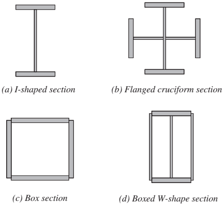
Figure description:
The image displays four types of structural column cross-sections:
- (a I-shaped section: Standard wide-flange or I-beam profile.
- (b Flanged cruciform section: A cross-shaped profile with flanges at the end of each arm.
- (c Box section: A hollow rectangular profile formed by four plates.
- (d Boxed W-shape section: An I-shaped profile enclosed within a rectangular box section.
Note: Plate preparation and welds are not illustrated in these diagrams.
Fig. C-2.1. Column shapes. Plate preparation and welds are not shown.
2.3.4 Isolation of Concrete Slab
Contact between the concrete slab and the face of the column or the face of connection elements can increase deformation demands on the beam bottom flange connection under positive bending (slab in compression). This increased demand is the result of composite action between the slab and the beam and from an upward shift in the neutral axis location. In some cases, this can cause a premature fracture at the beam bottom flange connection. To avoid premature failure, this section requires that the concrete slab be isolated in a manner that allows the beam to rotate with minimum engagement of the slab with the face of the column or face of connection elements. This requirement can be satisfied by providing a minimum of a 1 in. (25 mm) gap between the slab and the column on both sides of each flange, as shown in Figure C-2.2. A compressible fire-resistant material can be used to fill the gap. Where a connection element is present at the face of the column, the gap should be provided between the slab and the connection element, as shown in Figure C-2.2(b).
Slab isolation is not required for the reduced beam section (RBS), welded unreinforced flange-welded web (WUF-W), SidePlate, and Slotted Web moment connections because connection tests conducted on subassemblies with a composite slab demonstrated satisfactory performance without isolation of the concrete slab.