8.3.1 Beam Limitations
Beams shall satisfy the following limitations:
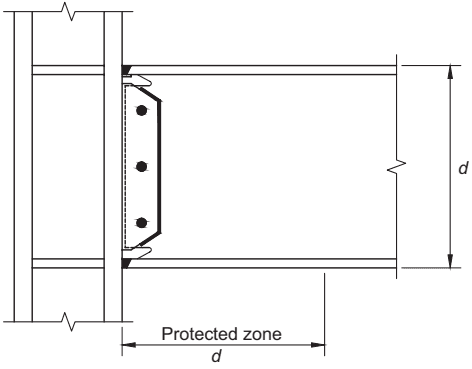
Figure description:
Key Entities and Details:
- Connection Type: WUF-W (Welded Unreinforced Flange-Welded Web moment connection.
- Beam: Horizontal steel member with a depth labeled as .
- Column: Vertical steel member supporting the beam.
- Welded Joints: Complete-joint-penetration (CJP groove welds connect the beam flanges to the column flange.
- Web Connection: A shear plate is welded to the column and bolted to the beam web with three bolts; the plate edges are also welded to the beam web.
- Protected Zone: Extends a distance from the face of the column along the length of the beam.
- Weld Access Holes: Clearly visible at the intersection of the beam flanges and web to facilitate welding.
Fig. 8.1. WUF-W moment connection.
- (1) Beams shall be rolled wide-flange or built-up I-shaped members conforming to the requirements of Section 2.3.
- (2) Beam depth is limited to a maximum of W36 (W920) for rolled shapes. Depth of built-up sections shall not exceed the depth permitted for rolled wide-flange shapes.
- (3) Beam weight is limited to a maximum of 150 lb/ft (220 kg/m).
- (4) Beam flange thickness is limited to a maximum of 1 in. (25 mm).
- (5) The clear span-to-depth ratio of the beam is limited as follows:
- (a) For SMF systems, 7 or greater.
- (b) For IMF systems, 5 or greater.
- (6) Width-to-thickness ratios for the flanges and web of the beam shall conform to the requirements of the AISC Seismic Provisions.
- (7) Lateral bracing of beams shall be provided as follows:
Lateral bracing of beams shall conform to the requirements of the AISC Seismic Provisions. To satisfy the requirements of the AISC Seismic Provisions for lateral bracing at plastic hinges, supplemental lateral bracing shall be provided at both the top and bottom beam flanges and shall be located at a distance of to from the face of the column, where is the depth of the beam. No attachment of lateral bracing shall be made to the beam in the region extending from the face of the column to a distance from the face of the column.
Exception: For both SMF and IMF systems, where the beam supports a concrete structural slab that is connected along the beam span between protected zones with welded shear connectors spaced at a maximum of 12 in. (300 mm) on center, supplemental top and bottom flange bracing at plastic hinges is not required.
- (8) The protected zone consists of the portion of beam between the face of the column and a distance one beam depth, , from the face of the column.
8.3.2 Column Limitations
Columns shall satisfy the following limitations:
-
(1) Columns shall be any of the rolled wide-flange shapes or built-up shapes permitted in Section 2.3.
-
(2) The beam shall be connected to the flange of the column.
-
(3) Rolled shape column depth shall be limited to a maximum of W36 (W920). The depth of built-up wide-flange columns shall not exceed that for rolled shapes. Flanged cruciform columns shall not have a width or depth greater than the depth allowed for rolled shapes. Built-up box columns shall not have a width or depth exceeding 24 in. (600 mm). Boxed wide-flange columns shall not have a width or depth exceeding 24 in. (600 mm) if participating in orthogonal moment frames.
-
(4) There is no limit on the weight per foot of columns.
-
(5) There are no additional requirements for flange thickness.
-
(6) Width-to-thickness ratios for the flanges and web of columns shall conform to the requirements of the AISC Seismic Provisions.
-
(7) Lateral bracing of columns shall conform to the requirements of the AISC Seismic Provisions.