2.4.1 Resistance Factors
A significant factor considered in the formulation of resistance factors is the occurrence of various limit states. Limit states that are considered brittle (nonductile) and subject to sudden catastrophic failure are typically assigned lower resistance factors than those that exhibit yielding (ductile) failure. Because, for the prequalified connections, design demand is determined based on conservative estimates of the material strength of weak elements of the connection assembly, and because materials,
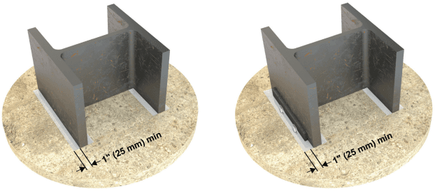
Figure description:
- Entity: Wide-flange (I-beam steel column section on a circular concrete-like base.
- Key Dimension: 1" (25 mm minimum clearance/extension from the outer edge of the column flange or attached hardware to the edge of the supporting surface.
- Diagram (Left: Shows the minimum distance measured directly from the column flange.
- Diagram (Right: Shows the minimum distance measured from an attached component (e.g., a backing bar or plate on the column flange.
(a) Column flange
(b) Connecting element at column flange
Fig. C-2.2. Separation of slab from column flange and connecting element at column flange.
workmanship, and quality assurance are more rigorously controlled than for other structural elements, resistance factors have been set somewhat higher than those tra- ditionally used. It is believed that these resistance factors, when used in combination with the design, fabrication, erection, and quality assurance requirements contained in this standard, will provide reliable service in the prequalified connections.
2.4.2 Plastic Hinge Location
For most prequalified connections, the intended behavior under earthquake loading is that inelastic deformation is developed primarily through flexural yielding of the beam—that is, through the development of a plastic hinge in the beam. For such prequalified connections, this standard specifies the presumed location of the plastic hinge. In reality, the formation of a plastic hinge requires flexural yielding over some length of the beam. Defining a single point as the plastic hinge location is therefore an idealization of actual behavior, but it is a useful concept for purposes of analysis and design. The plastic hinge locations specified herein are based on observed behavior during connection assembly tests and analysis of the connection, and they are generally at or near the locations of the largest ratio of flexural demand-to-capacity in the beam when the frame is subjected to lateral load. For each connection, the design procedure and design parameters are adjusted based on the specified plastic hinge location.
For the Simpson Strong-Tie Strong Frame connection and the DuraFuse Frames connection, the intended behavior under earthquake loading is that inelastic deformation is developed by yielding of connection elements rather than by flexural yielding of the beam. Consequently, the concept of a plastic hinge in the beam is not applicable to these connections.
2.4.3 Probable Maximum Moment at Plastic Hinge
The probable plastic moment at the plastic hinge is intended to be a conservative estimate of the maximum moment likely to be developed in the beam at the plastic hinge location under cyclic inelastic loading. It includes consideration of likely material overstrength, accounted for by the factor , and the effects of strain hardening and other factors that may affect the ultimate flexural strength of the plastic hinge, accounted for in the factor . The value specified for for each connection is based on an evaluation of connection test data.
2.4.4 Shear Force at Plastic Hinge
A number of the prequalified connections require calculation of the shear force at the plastic hinge, , as defined in this section. is the shear force at the plastic hinge location when the bending moment at the plastic hinge is equal to the probable maximum moment, , and with the applicable gravity load acting on the beam. can be determined from a free-body diagram of the segment of the beam between plastic hinge locations. An example is shown in Figure C-2.3 for the case of a uniform gravity load on the beam and for the case where is applied in a counterclockwise direction. The shear force at each plastic hinge due to acting at the plastic hinge locations is equal to . The shear force due to the gravity load, for this example, has the same sign as at the left end of the free-body diagram and is of the opposite sign at the other end. Consequently, the shear force at each end of the free-body diagram is different. is taken as the larger of these two values, as shown in the figure. Because can reverse direction, can occur at both ends of the free-body diagram. For gravity loads on the beam other than a uniform load, the shear force due to gravity load can be determined directly from equilibrium of the free-body diagram.
2.4.5 Probable Maximum Moment at Face of Column
A number of the prequalified connections require calculation of the probable maximum moment at the face of the column, , as defined in this section. is the bending moment at the face of the column when the bending moment at the plastic hinge is equal to the probable maximum moment, , and the shear force at the plastic hinge is can be determined from a free-body diagram of the portion of the beam between the plastic hinge location and the face of the column, as illustrated in Figure C-2.4. The equation for given in this figure and also shown as Equation 2.4-4 neglects the gravity load on the portion of the beam between the plastic hinge location and the face of the column because this typically has a negligible contribution to .
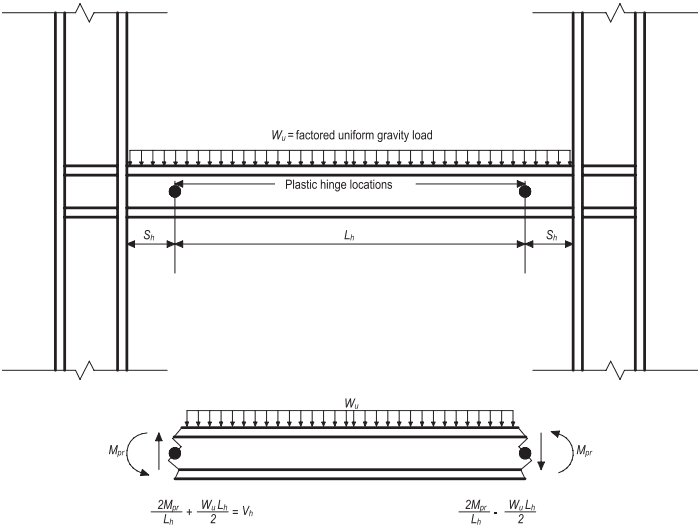
Figure description:
Key Information:
- Subject: Engineering schematic and free-body diagram (Fig. C-2.3 used to determine shear force ( at plastic hinge locations in a beam-column assembly.
- Key Entities & Variables:
- Plastic hinge locations: Indicated by black dots on the beam, where yielding is expected.
- : Factored uniform gravity load applied across the beam.
- : The clear span distance between the two plastic hinge locations.
- : The distance from the column face to the center of the plastic hinge.
- : Probable maximum moment acting at the plastic hinge locations.
- : Resultant shear force at the plastic hinge.
- Mathematical Relationships:
- The diagram provides equations for calculating shear based on the moment and gravity load:
- Left hinge shear:
- Right hinge shear component:
- The diagram provides equations for calculating shear based on the moment and gravity load:
Fig. C-2.3. Free-body diagram for determination of .