Double-tee connections are prequalified for use in special moment frame (SMF) and intermediate moment frame (IMF) systems within the limitation of these provisions.
Exception: Double-tee connections in SMF systems with concrete structural slabs are prequalified only if the concrete slab is isolated in accordance with Section 2.3.4.
User Note: Note that connections designed for use in SMF and IMF systems must be designed as fully restrained (FR) connections. It is possible to design double-tee connections that qualify as partially restrained (PR), even when they satisfy all of the strength requirements stipulated within this specification. As a result, care must be taken during design to ensure that the connections resulting from this chapter have not only adequate strength, but that they also have adequate stiffness.
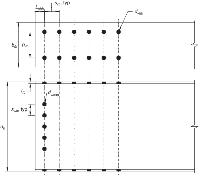
Figure description:
Key Technical Entities and Dimensions: Fig. 13.4
General Context:
- Subject: Structural steel beam dimensions for double-tee connections.
- Purpose: Detailing hole patterns and spacing for bolt placement in SMF/IMF systems.
Top View (Flange Details:
- : Width of the beam flange.
- : Gauge distance between the two rows of flange bolts.
- : End distance from the beam edge to the first row of bolts.
- : Typical longitudinal spacing between rows of flange bolts.
- : Diameter of the bolt holes in the flange.
Side Elevation View (Web/Overall Details:
- : Total depth of the beam.
- : Thickness of the beam flange.
- : Typical vertical spacing between bolt holes in the web.
- : Diameter of the bolt holes in the web.
Fig. 13.4. Additional beam dimensions for double-tee connections.
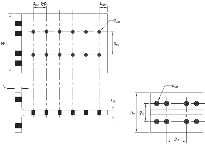
Figure description:
Key Information: T-stub Dimensions for Double-Tee Connections
The image provides technical specifications for a T-stub component used in structural connections, showing top, side, and end views.
Key Dimensions and Parameters:
- : Overall width of the T-stub flange.
- : Flange width (perpendicular to .
- : Thickness of the flange.
- : Thickness of the stem.
- : Diameter of bolt holes in the stem.
- : Diameter of tension bolt holes in the flange.
- : Typical vertical spacing between bolt holes in the stem.
- : Gage distance between rows of holes in the stem.
- : Gage distance between rows of tension holes in the flange.
- : Gage distance between inner columns of tension holes in the flange.
- : Edge distance from the last stem hole to the end of the plate.
Fig. 13.5. T-stub dimensions for double-tee connections.
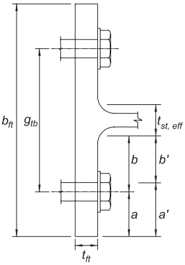
Figure description:
This image is a technical diagram illustrating the flange dimensions of a T-stub for double-tee connections.
Key Dimensions and Entities:
- : Total width of the T-stub flange.
- : Thickness of the T-stub flange.
- : Gauge distance between the centerlines of the two bolts.
- : Effective thickness of the T-stub stem.
- : Distance from the face of the stem to the centerline of the bolt.
- : Distance from the centerline of the bolt to the edge of the flange.
- : Adjusted distance from the face of the stem to the center of the bolt hole (typically used in prying action calculations.
- : Adjusted distance from the center of the bolt hole to the edge of the flange.
- Bolts: Two bolts are shown securing the T-stub flange to another component.
Fig. 13.6. T-stub flange dimensions for double-tee connections.