The SidePlate® moment connection is a post-Northridge connection system that uses a configuration of redundant interconnecting structural plates, fillet weld groups, and high-strength pretensioned bolts (as applicable), which act as positive and discrete load transfer mechanisms to resist and transfer applied moment, shear, and axial load from the connecting beam(s) to the column. This load transfer minimizes highly restrained conditions and triaxial strain concentrations that typically occur in flange-welded moment connection geometries. The connection system is used for both new and retrofit construction and for a multitude of design hazards such as earthquakes, extreme winds, and blast and progressive collapse mitigation.
The wide range of applications for SidePlate connection technology, including the methodologies used in the fabrication and erection shown herein, are protected by one or more U.S. and foreign patents identified at the bottom of the first page of Chapter 11. Information on the SidePlate moment connection can be found at www .sideplate.com. SidePlate moment connections not specifically designed by SidePlate Systems Inc. are considered unauthorized and not prequalified and should not be manufactured.
SidePlate moment connections are designed and detailed in two types:
- (1) Field-welded connection
- (2) Field-bolted connection
Both types are fully restrained connections of beams to columns conforming to Section 2.2. Figures 11.1 and 11.2 show the field-welded and field-bolted connections' various configurations, respectively. The field-bolted connection is available in three configurations as shown in Figure 11.3: configuration A (standard), configuration B (narrow), and configuration C (tuck). The field-bolted connection is also referred to as the SidePlate Plus Connection.
Moment frames that utilize the SidePlate connection system may be constructed using one of three methods. The most common construction method uses a full-length beam for erection—namely, SidePlate FRAME® configuration—as shown in Figure C-11.1(a) and (b). This method employs a full-length beam assembly consisting of the beam with shop-installed cover plates {B}/angles {H} (if required) and vertical shear elements (as applicable), which are either fillet-welded or bolted near the ends of the beam depending on the type of the connection.
Column assemblies are typically delivered to the job site with the horizontal shear plates {D} (as applicable) and side plates {A} shop welded to the column at the proper floor framing locations. Where built-up box columns or HSS columns are used, horizontal shear plates {D} are not required nor applicable.
For the field-welded option: During frame erection, the full-length beam assemblies are lifted up in between the side plates {A} that are kept spread apart at the top edge of the side plates {A} with a temporary shop-installed spreader [Figure C-11.1(a)]. A few bolts connecting the beam’s vertical shear plates {C} (shear elements as applicable) to adjacent free ends of the side plates {A} are initially inserted to provide temporary shoring of the full-length beam assembly, after which the temporary spreader is removed. The remaining erection bolts (as many as can be installed) are then inserted and installed to a snug-tight condition. These erection bolts can also act as a clamp to effectively close or minimize potential root gaps that might have existed between the interior face of the side plates {A} and the longitudinal edges of the top cover plate {B}, while bringing the top face of the wider bottom cover plate {B} into a snug fit with the bottom edges of the side plates {A}. To complete the field assembly, four horizontal fillet welds joining the side plates {A} to the cover plates {B} are then deposited in the horizontal welding position (position 2F per AWS D1.1/ D1.1M), and, when applicable, two vertical single-pass field fillet welds joining the side plates {A} to the vertical shear elements (VSE) are deposited in the vertical welding position (position 3F per AWS D1.1/D1.1M). Alternately, this can be configured such that the width of bottom cover plate {B} is equal to the width of the top cover plate {B} (i.e., both cover plates {B} fit within the separation of the side plates {A}, which would also be slightly deeper in their lengths to accommodate), in lieu of the bottom cover plate {B} being wider than the distance between side plates {A}. Note that when this option is selected by the engineer, the two bottom fillet welds connecting the bottom cover plates {B} to the side plates {A} will be deposited in the overhead welding position (position 4F per AWS D1.1/D1.1M).
For the field-bolted option: During frame erection, the full-length beam assemblies are typically dropped down in between the side plates {A} that are kept spread apart at the bottom edge of the side plates {A} with a temporary shop-installed spreader [Figure C-11.1(b)]. A few bolts/fasteners assemblies connecting the beam’s top cover plate {B} (or vertical shear plates {C} as applicable) to adjacent free ends of the longitudinal angles on the side plates {A} (or the side plates {A} themselves) are initially inserted to provide temporary shoring of the full-length beam assembly, after which the temporary spreader is removed. Shim plates may be installed between the side plates {A} and the cover plate {B} or longitudinal angles if required. The remaining bolts/fastener assemblies are then inserted to a snug-tight specification in a systematic assembly within the joint, progressing from the most rigid part of the joint until the connected plies are in as firm as contact as practicable. These bolts should clamp and effectively minimize any gaps that might have existed between the interior face of the side plates {A} and the longitudinal edges of the angles and that of the interface between the bottom face of the top cover plate {B} and the top longitudinal angles {G} on the exterior face of the side plates {A} (configuration A and configuration C). If the gaps are not closed during this process, it is acceptable to use a full length shim plate up to ¼ in. (6 mm) without penalty. Gaps that cannot be closed that are greater than ¼ in. (6 mm) should be documented, and SidePlate Systems Inc. should be contacted for further consultation. Note that the standard and tuck configurations (configuration A and configuration C) have a pair of angles attached to the bottom flange of the beam, and the narrow configuration (configuration B) consists of pairs of angles attached to both the top and bottom flanges of the beam. To complete the field assembly, the second step of the pretensioning methodology is the subsequent systematic pretensioning of all bolt/fastener assemblies; they progress in a similar manner as was done for the snug-tight condition, from the most rigid part of the joint that will minimize relaxation of previously pretensioned bolts.
Where the full-length beam erection method (SidePlate FRAME configuration) is not used, the original SidePlate moment configuration may be used (second method). The original SidePlate moment configuration utilizes the link-beam erection method, which connects a link beam assembly to the beam stubs of two opposite column tree assemblies with field CJP groove welds [Figures C-11.1(c) and 11.1(d)]. As a third method, in cases where moment frames can be shop prefabricated and shipped to the site in one piece, no field bolting or welding is required [Figure C-11.1(e)].
The SidePlate moment connection is proportioned to develop the probable maximum moment of the connected beam. Beam flexural, axial, and shear forces are typically transferred to the top and bottom rectangular cover plates {B} via four shop horizontal fillet welds that connect the edges of the beam flange tips to the corresponding face of each cover plate {B} (two welds for each beam flange). When the U-shaped cover plates {B} or angles {H} are used, the same load transfer occurs via four shop horizontal fillet welds that connect the edge of the beam flange tips to the corresponding face of each cover plate {B}/angles {H} (two welds for each beam flange), as well as two shop horizontal fillet welds that connect the outside faces of the beams top and bottom flanges to the corresponding inside edge of each U-shaped cover plate {B} (for the conditions with pairs of angles {H}, there are two welds that will connect each angle to the corresponding beam flange face). These same forces are then transferred from the cover plates {B} or pairs of angles {H} to the side plates {A} via either four field horizontal fillet welds (in the field-welded connection) or four lines of bolts (in the field-bolted connection) that connect the cover plates {B} or pairs of angles {H} to the side plates {A}. The side plates {A} transfer all of the forces from the beam (including that portion of shear in the beam that is transferred from the web of the beam via vertical shear elements, as applicable, or via the cover plate {B} and pairs of angles {H}, as applicable) across the physical gap to the column via shop fillet welding (or flare bevel welding, as required) of the side plates {A} to the column flange tips (a total of four shop fillet welds; two for each side plate {A}), and to complete the weld group, there are two horizontally placed shop fillet welds at the top and bottom of each side plates {A}. These welds may attach directly to the face of a box or HSS column, or they may attach to horizontal shear plates {D} as applicable (a total of four shop fillet welds two for each side plate {A}). The horizontal shear plates {D} are, in turn, shop fillet welded to the column web and under certain conditions, also to the inside face of column flanges.
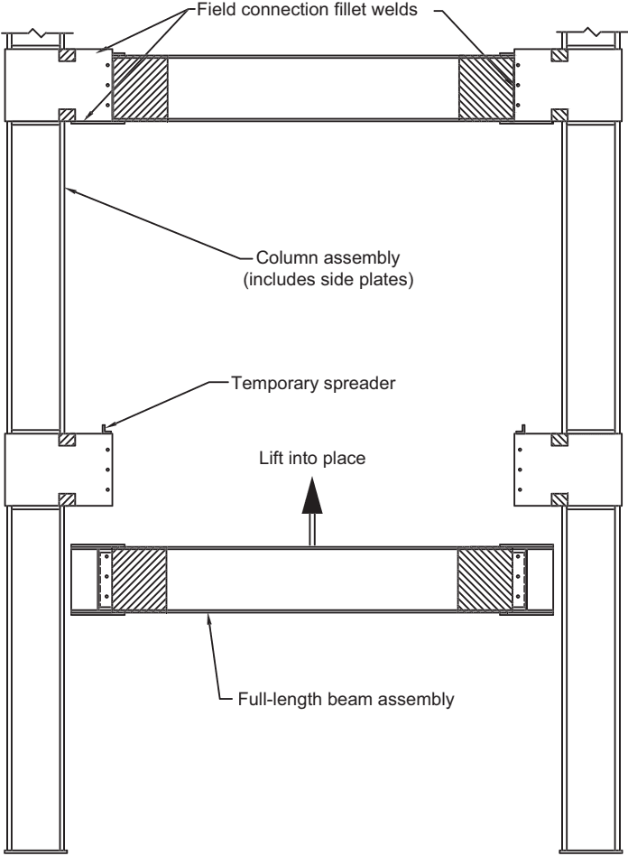
Figure description:
Key Entities and Details:
- Full-length beam assembly: The horizontal structural element being "lifted into place."
- Column assembly: Vertical supports that include integrated side plates.
- Field connection fillet welds: Specified locations where the beam is welded to the column assembly in the field.
- Temporary spreader: Used to assist in the positioning and alignment of the beam during erection.
- Configuration: SidePlate FRAME configuration utilizing a field-welded erection method.
Full-length beam erection method (SidePlate FRAME configuration, field welded)
Fig. C-11.1(a). SidePlate moment connection construction methods.
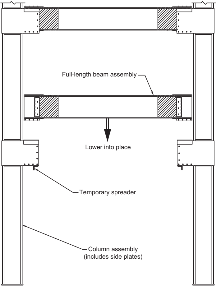
Figure description:
Method: Full-length beam erection (SidePlate moment standard configuration, field bolted.
Key Components:
- Column assembly: Vertical supports including pre-attached side plates.
- Full-length beam assembly: Horizontal structural member being installed.
- Temporary spreader: Support component on the column assembly to aid beam placement.
Process:
- The full-length beam assembly is lowered into place between two established column assemblies.
- The final assembly utilizes field-bolted connections at the side plates.
Full-length beam erection method (SidePlate moment standard configuration, field bolted)
Fig. C-11.1(b). SidePlate moment connection construction methods.
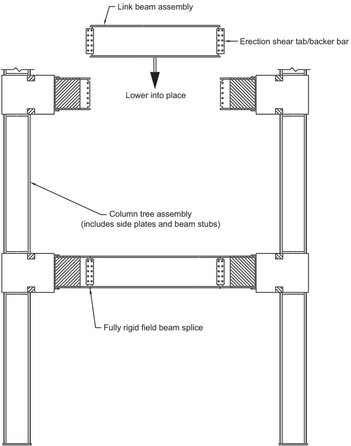
Figure description:
- Method: Link-beam erection (field welded Side Plate moment configuration.
- Link Beam Assembly: Central beam section featuring erection shear tabs/backer bars at both ends; lowered into place between supports.
- Column Tree Assembly: Vertical columns integrated with side plates and horizontal beam stubs.
- Connection: Link beam connects to beam stubs via a fully rigid field beam splice.
Link-beam erection method (original SidePlate moment configuration, field welded)
Fig. C-11.1(c). SidePlate moment connection construction methods.
SidePlate Systems developed, tested, and validated the SidePlate moment connection design methodology, design controls, critical design variables, and analysis procedures. The development of the SidePlate FRAME configuration that employs the full-length beam erection method builds off the research and testing history of its proven predecessor—the original configuration and its subsequent refinements. Moreover, in 2015–2017, the uniaxial field-bolted connection was developed and successfully tested and validated. In 2018, the biaxial version of the SidePlate connection with HSS and built-up box columns was developed and tested. It resulted
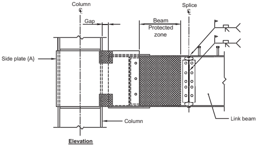
Figure description:
Image Type: Engineering schematic (Elevation view of a link beam-to-beam stub splice detail.
Key Entities:
- Column: Main vertical support member with a defined centerline.
- Side plate {A}: Part of the SidePlate moment connection system attached to the column.
- Link beam: Horizontal structural member connected via the splice.
Technical Details:
- Gap: Specified spacing between the column face and the beam assembly.
- Beam Protected Zone: A designated cross-hatched area on the beam.
- Splice: A vertical junction featuring bolted plates and weld symbols, aligned on a splice centerline.
- Welding Symbols: Indicate specific field welding requirements at the splice location.
(d) Link beam-to-beam stub splice detail
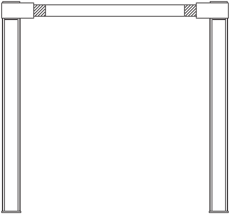
Figure description:
Image Type: Technical structural diagram
Key Entities:
- Vertical Columns: Two vertical structural members supporting the frame.
- Horizontal Beam: A single beam spanning between the two columns.
- Stub Splice Details: Hatched rectangular regions near the beam ends indicating the splice locations between the beam and the column stubs.
Key Information:
- Structure: A shop-prefabricated, single-story moment frame.
- Construction Method: Designed for assembly without field welding; the connections are shop-prefabricated.
- Splice Location: Features link beam-to-beam stub splices located away from the primary column-to-beam joints.
(e) All shop-prefabricated single-story moment frame (no field welding); multistory frames dependent on transportation capabilities
Fig. C-11.1(d-e). SidePlate moment connection construction methods.
in further performance enhancements: optimizing the use of connection component materials with advanced analysis methods and maximizing the efficiency, simplicity, and quality control of its fabrication and erection processes. Following the guidance of the AISC Seismic Provisions, the validation of the field-welded and field-bolted SidePlate FRAME configuration consists of:
-
(1) Analytical testing conducted by SidePlate Systems Inc. using nonlinear finite element analysis (FEA) for built-up and rolled shapes, plates, bolts, and welds and validated inelastic material properties by physical testing.
-
(2) In addition to the tests conducted between 1994 and 2006 utilizing the original configuration, SidePlate Systems conducted physical validation testing with full-length beam assembly (SidePlate FRAME configuration) at the Lehigh University Center for Advanced Technology for Large Structural Systems (ATLSS) in 2010 (Hodgson et al., 2010a, 2010b, and 2010c; a total of six cyclic tests) and at the University of California, San Diego (UCSD), Charles Lee Powell Laboratories, in 2012 and 2013 (Minh Huynh and Uang, 2012; a total of two cyclic tests; and Minh Huynh and Uang, 2013; a total of one biaxial cyclic test). The biaxial moment connection test subjected the framing in the orthogonal plane to a constant shear, creating a moment across the column-beam joint equivalent to that created by the probable maximum moment at the plastic hinge of the primary beam, while the framing in the primary plane was simultaneously subjected to the qualifying cyclic loading specified by the AISC Seismic Provisions (AISC, 2016a). Also, a physical testing program was conducted at UCSD (Mashayekh and Uang, 2016; Reynolds and Uang, 2017) to validate the performance of the field-bolted SidePlate moment connection. A total of seven cyclic tests—two of which utilized HSS columns and one of which utilized a built-up box column—were conducted. The purpose of these tests was to confirm adequate global inelastic rotational behavior of either field-welded or field-bolted SidePlate moment connections with parametrically selected member sizes, corroborated by analytical testing, and to identify, confirm, and accurately quantify important limit state thresholds for critical connection components to objectively set critical design controls. The 2015–2017 testing program at UCSD additionally aimed to verify the satisfactory performance of HSS columns with a width-to-thickness ratio of up to 21 in SidePlate moment connections through the application of a significant axial load on the column in addition to the AISC Seismic Provisions loading protocol. The testing program also attempted to verify the satisfactory performance of SidePlate moment connections with built-up box columns without any internal horizontal shear plates {D} or stiffeners (continuity plates), where flange and web plates of built-up box columns are continuously connected by either fillet welds or PJP groove welds along the length of the column. It implies that no CJP welds will be required within a zone extending from 12 in. (300 mm) above the upper beam flange to 12 in. (300 mm) below the lower beam flange, flange, and web plates of boxed wide-flange columns in SidePlate moment connections. More recently, a full-scale testing program including four biaxial tests and one uniaxial test with HSS and built-up box columns, was successfully conducted at UCSD (Reynolds and Uang, 2018). Two of the biaxial tests utilized the newly developed tuck configuration (configuration C) with a built-up wide-flange beam with no vertical shear element. The width-to-thickness ratio of the HSS column was 19.9, confirming the satisfactory performance of HSS columns with a width-to-thickness ratio of up to 21 once again.
-
(3) Tests on SidePlate moment connections, both uniaxial and biaxial applications, show that yielding is generally concentrated within the beam section just outside the ends of the two side plates {A}. Peak strength of specimens is typically achieved at an interstory drift angle of approximately 0.03 to 0.05 rad. Specimen strength then gradually reduces due to local and lateral-torsional buckling of the beam. Ultimate failure typically occurs at interstory drift angles of approximately 0.04 to 0.06 rad for the field-welded and 0.06 to 0.08 rad for the field-bolted connection by low-cycle fatigue fracture from local buckling of the beam flanges and web.
To ensure predictable, reliable, and safe performance of the SidePlate FRAME configuration when subjected to severe load applications, the inelastic material properties, finite element modeling (FEM) techniques, and analysis methodologies that were used in its analytical testing were initially developed, corroborated, and honed based on nonlinear analysis of prior full-scale physical testing of the original SidePlate configuration. The finite element techniques and design methodologies have been further refined and polished as a result of the testing program with field-bolted connections at UCSD in 2015–2017.
The earliest physical testing of SidePlate connections consisted of a series of eight uniaxial cyclic tests, one biaxial cyclic test conducted at UCSD, and a separate series of large-scale arena blast tests. The blast tests consisted of an explosion followed by monotonic loading using the following configurations: two blast tests (one with and one without a concrete slab present), two blast-damaged progressive collapse tests, and one non-blast damaged test—all conducted by the Defense Threat Reduction Agency (DTRA) of the U.S. Department of Defense (DoD), at Kirtland Air Force Base, Albuquerque, N.M.
These extensive testing efforts have resulted in the ability of SidePlate Systems to:
- (1) Reliably replicate and predict the global behavior of the SidePlate FRAME configurations compared to actual tests.
- (2) Explore, evaluate, and determine the behavioral characteristics, redundancies, and critical limit state thresholds of its connection components.
- (3) Establish and calibrate design controls and critical design variables of the Side-Plate FRAME configurations, as validated by physical testing.
Connection prequalification is based on the completion of several carefully prescribed validation testing programs, the development of a safe and reliable plastic capacity design methodology that is derived from ample performance data from
36 full-scale tests, of which six were biaxial, and the judgment of the CPRP. The connection prequalification objectives have been successfully completed; the rudiments are summarized in the following:
- (1) System-critical limit states have been identified and captured by physical full-scale cyclic testing and corroborated through nonlinear FEA.
- (2) The effectiveness of identified primary and secondary component redundancies of the connection system has been demonstrated and validated through parametric performance testing—both physical and analytical.
- (3) Critical behavioral characteristics and performance nuances of the connection system and its components have been identified, captured, and validated.
- (4) Material submodels of inelastic stress/strain behavior and fracture thresholds of weld consumables and base metals have been calibrated to simulate actual behavior.
- (5) Sufficient experimental and analytical data on the performance of the connection system have been collected and assessed to establish the likely yield mechanisms and failure modes.
- (6) Rational nonlinear FEA models for predicting the resistance associated with each mechanism and failure mode have been employed and validated through physical testing.
- (7) Based on the technical merit of the preceding accomplishments, a rational ultimate strength design procedure has been developed based on physical testing, providing confidence that sufficient critical design controls have been established to preclude the initiation of undesirable mechanisms and failure modes and to secure expected safe levels of cyclic rotational behavior and deformation capacity of the connection system for a given design condition.