14.3.1 Beam Limitations
Beams shall satisfy the following limitations:
- (1) Beams shall be rolled wide-flange or built-up I shaped members conforming to the requirements of Section 2.3.
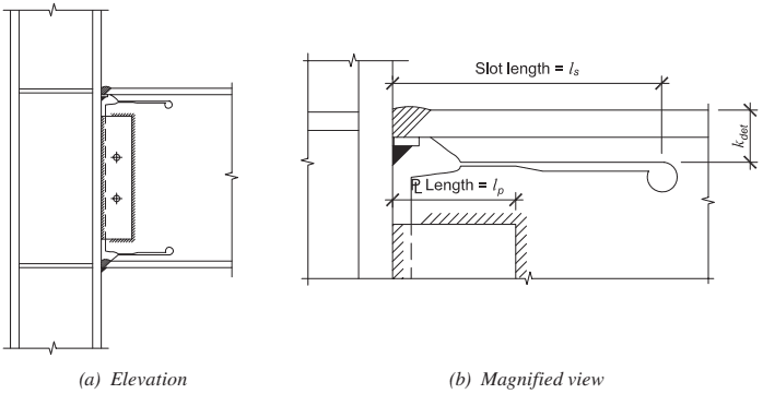
Figure description:
Fig. 14.1. SW beam-to-column moment connection
Key Components and Features:
- (a Elevation View: Displays a structural steel connection between a vertical column and a horizontal beam. Features include a shear tab with two bolts and welded flange-to-column joints.
- (b Magnified View: Details the specific geometry of a slotted web connection.
- Key Dimensional Parameters:
- (Slot length: Total horizontal length of the cutout in the beam.
- (Plate length: Length of the connection plate relative to the column face.
- : Vertical distance from the outer face of the beam flange to the slot.
- Entities: Structural column, beam, shear plate, fillet/groove welds, and a longitudinal slot with a radiused end.
Fig. 14.1. SW beam-to-column moment connection.
- (2) Beam depth shall be limited to a maximum of W36 (W920) for rolled shapes. The depth of built-up sections shall not exceed the depth permitted for rolled wide-flange shapes.
- (3) Beam weight shall be limited to a maximum 400 lb/ft (600 kg/m).
- (4) Beam flange thickness shall be limited to a maximum of 2¼ in. (56 mm).
- (5) The clear span-to-depth ratio of the beam shall be limited to 6.4 or greater.
- (6) Width-to-thickness ratios for the flanges and webs of the beam shall conform to the requirements of the AISC Seismic Provisions.
- (7) Lateral bracing of the beams shall be provided in conformance with the AISC Seismic Provisions. No supplemental lateral bracing is required at the plastic hinges.
- (8) The protected zones as shown in Figure 14.2 consist of the following:
- (a) The portion of the beam web between the face of the column to the end of the slots plus one-half the depth of the beam, d, beyond the slot end, and
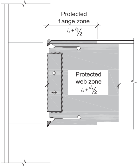
Figure description:
Subject: Structural steel beam-to-column connection highlighting protected zones.
Protected Zones:
- Protected Flange Zone: Shaded regions on the beam flanges extending a distance of from the column face.
- Protected Web Zone: Large shaded region on the beam web extending a distance of from the column face.
Key Structural Components:
- Vertical Column: H-shaped steel section.
- Horizontal Beam: I-shaped steel section connected to the column flange.
- Shear Connection: Bolted shear plate with two bolts connecting the beam web to the column.
- Welds: Beam flanges are welded to the column face; includes weld access holes at the web-flange intersections.
Fig. 14.2. Protected zones.
- (b) The beam flange from the face of the column to the end of the slot plus one-half the beam flange width, .
14.3.2 Column Limitations
- (1) Columns shall be of any of the rolled wide-flange shapes or built-up shapes permitted in Section 2.3.
- (2) The beam shall be connected to the flange of the column.
- (3) Rolled-shape column depths shall be limited to W36 (W920). The depth of built-up wide-flange columns shall not exceed that allowed for rolled shapes. Flanged cruciform columns shall not have a width or depth greater than the depth allowed for rolled shapes. Built-up box columns shall not have a width or depth exceeding 24 in. (600 mm). Boxed wide-flange columns shall not have a width or depth exceeding 24 in. (600 mm) if participating in orthogonal moment frames.
- (4) There is no limit on the weight per foot of columns.
- (5) There are no additional requirements for flange thickness.
- (6) Width-thickness ratios for the flanges and web of columns shall conform to the requirements of the AISc Seismic Provisions.
- (7) Lateral bracing of columns shall conform to the requirements of the AISC Seismic Provisions.