The bolted flange plate (BFP) connection is a field-bolted connection. The fundamental seismic behaviors expected with the BFP moment connection include:
- (1) Initial yielding of the beam at the last bolt away from the face of the column.
- (2) Slip of the flange plate bolts, which occurs at similar resistance levels to the initial yielding in the beam flange, but the slip does not contribute greatly to the total deformation capacity of the connection.
- (3) Secondary yielding in the column panel zone, which occurs as the expected moment capacity and strain hardening occur.
- (4) Limited yielding of the flange plate, which may occur at the maximum deformations.
This sequence of yielding has resulted in very large inelastic deformation capacity for the BFP moment connection, but the design procedure is somewhat more complex than some other prequalified connections.
The flange plates and web shear plate are shop-welded to the column flange and field-bolted to the beam flanges and web, respectively. ASTM F3125/F3125M Grade A490 or A490M bolts with threads excluded from the shear plane are used for the beam flange connections because the higher shear strength of the Grade A490 or A490M bolts reduces the number of bolts required and reduces the length of the flange plate. The shorter flange plates that are, therefore, possible reduce the seismic inelastic deformation demands on the connection and simplify the balance of the resistances required for different failure modes in the design procedure. Flange plate connections with ASTM F3125/F3125M Grade A325 or A325M bolts may be possible but will be more difficult to accomplish because of the reduced bolt strength, greater number of bolts, and longer flange plates required. As a result, the connection is not prequalified for use with Grade A325 or A325M bolts.
Prequalification of the BFP moment connection is based upon 20 BFP moment connection tests under cyclic inelastic deformation (FEMA, 2000e; Schneider and Teeraparbwong, 1999; Sato et al., 2008). Additional evidence supporting prequalification is derived from bolted T-stub connection tests (FEMA, 2000e; Swanson et al., 2000) because the BFP moment connection shares many yield mechanisms, failure modes, and connection behaviors with the bolted T-stub connection. The tests were performed under several deformation-controlled test protocols, but most use variations of the ATC-24 (ATC, 1992) or the SAC steel protocol (Krawinkler et al., 2000), which are both very similar to the prequalification test protocol of AISC Seismic Provisions Chapter K. The 20 BFP tests were performed on connections with beams ranging in depth from W8 (W200) to W36 (W920) sections, and the average total demonstrated ductility capacity exceeded 0.057 rad.
Most past tests have been conducted on specimens with single-sided connections, and the force-deflection behavior is somewhat pinched as shown in Figure C-7.1. Because plastic hinging at the end of the flange plate is the controlling yield mechanism, the expected plastic moment at this location dominates the connection design. The pinching is caused by a combination of bolt slip and the sequence of yielding and strain hardening encountered in the connection. Experiments have shown that the expected peak moment capacity at the plastic hinge is typically on the order of 1.15 times the expected of the beam, as defined in the AISC Seismic Provisions, and the expected moment at the face of the column is on the order of 1.3 to 1.5 times the expected of the beam, depending upon the span length, number of bolts, and length of the flange plate. The stiffness of this connection is usually slightly greater than of that anticipated with a truly rigid, fully restrained (FR) connection. This reduced stiffness is expected to result in elastic deflection no more than larger than computed with an FR connection, and thus elastic calculations with rigid connections are considered to be adequate for most practical design purposes.
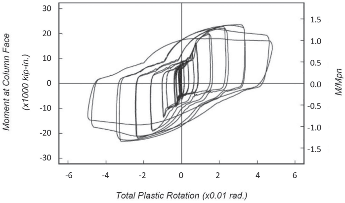
Figure description:
Moment at Column Face vs. Total Plastic Rotation
Moment at Column Face vs. Total Plastic Rotation
| Total Plastic Rotation (x0.01 rad.) | Moment at Column Face (x1000 kip-in.) | M/Mpn |
|---|---|---|
| -4.8 | -15.0 | -0.75 |
| -4.0 | -20.0 | -1.00 |
| -2.5 | -23.0 | -1.15 |
| -1.0 | -12.0 | -0.60 |
| 0.0 | -8.0 | -0.40 |
| 1.0 | 12.0 | 0.60 |
| 2.2 | 22.0 | 1.10 |
| 3.2 | 23.5 | 1.18 |
| 4.5 | 20.0 | 1.00 |
| 5.2 | 16.0 | 0.80 |
| 4.0 | -2.0 | -0.10 |
| 2.0 | -5.0 | -0.25 |
| 0.0 | -12.0 | -0.60 |
| -1.5 | -20.0 | -1.00 |
| -3.0 | -23.0 | -1.15 |
| -4.5 | -18.0 | -0.90 |
| -5.0 | -14.0 | -0.70 |
Notes: The chart displays a hysteretic response with multiple cycles. The provided data points represent the envelope of the outer loops. The relationship between the two Y-axes is M/Mpn = Moment / 20.0.
Fig. C-7.1. Moment at face of column versus total connection rotation for a BFP moment connection with a W30x108 (W760x161) beam and a W14x233 (W360x347) column.